Hello, I need to create a material that is a sandstone block texture on the bottom and limestone on the top. I cannot bake it since it has to be reused in many different meshes and it should tile seamless since the meshes are big (the two textures are already seamless).
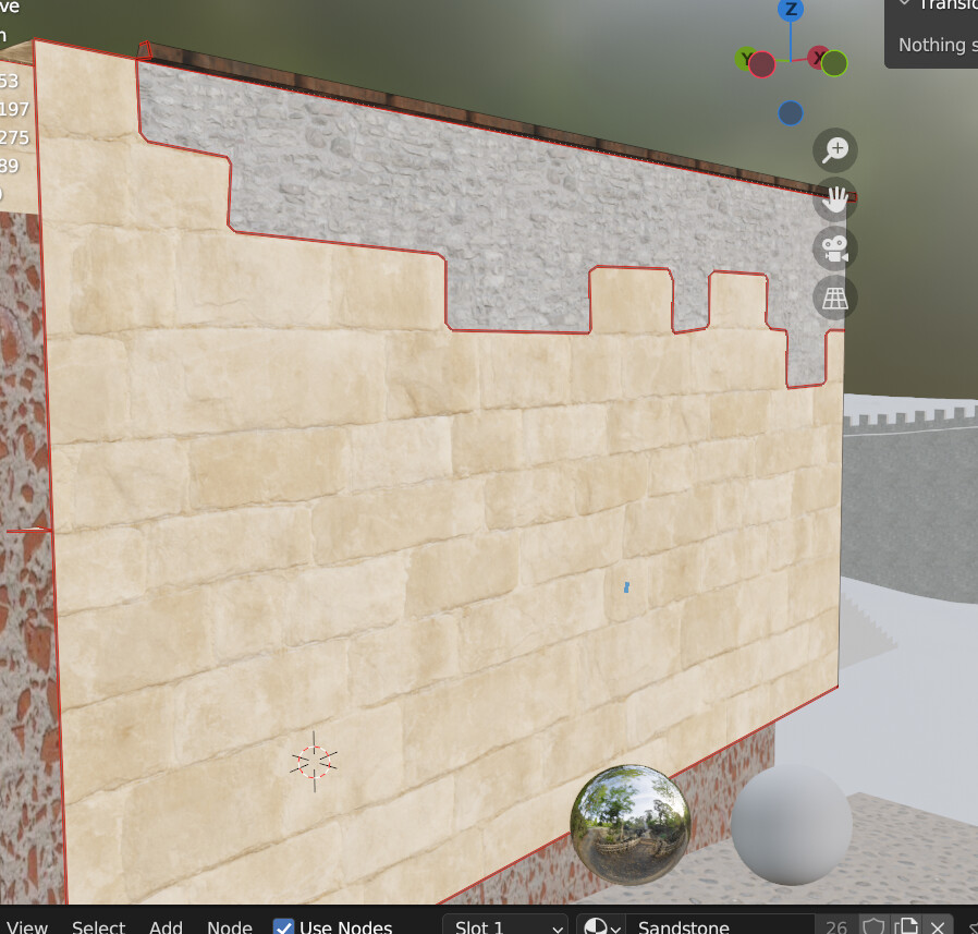
In the next screenshot you can see how it would be. In this case I have simply applied the sandstone block material (yellow) and used the knife tool to cut around the blocks, then I have applied the limestone material (grey) on the other half. This of course creates a huge NGon. Also, any modification to the size of the wall, means to have to unwrap again, and all the stones would be moved, making me have to cut the shape again. This also needs 2 different materials, but it is not a big deal for me.
Maybe using a decal for the sandstone blocks and overlap it with the limestone wall. The limestone (grey) is already seamless so I could tile it as much as I want, and the sandstone would be an alpha texture that would also tile seamlessly but only on the X axis (horizontally), so that I could place it at the bottom of every wall.
Vertex colors: the problem is that it mixes the two textures (it is not a sharp change between one and another), plus it is hard to control which sandstone blocks get cut and how, which makes it look bad since stones are cut in half.
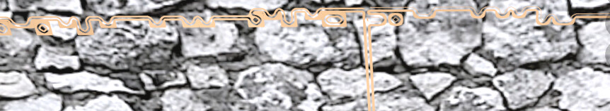
Custom texture: in GIMP make a trim that tiles in the X axis only, and make it follow a pattern like in the screenshot. The downside is that it could not tile in the Y axis obviously, so for tall surfaces like a taller wall it would be hard to make the texture fit the mesh.
With vertex color, you can control the transition sharpness with a color ramp or RGB curve.
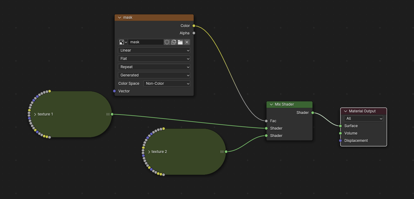
If you want to control exactly on which stone the transition happens then you simply need a 3rd grey scale image texture that’s used as mask (for example to control the mix shader factor).
It sounds a bit like that you want too much from a single material. That’s probably the reason why you struggle to find a one-size-fits-all solution here.
Since you seem to have huge walls which you want to modify depending on where to place them, I would go the vertex paint way. That’s how it’s done for many large assets in games.
Make sure both your sandstone and limestone materials a tileable materials. Give your wall pieces sufficient geometry. This way you can better control your painting (more vertices to paint on). You can modify/modulate the transition inbetween the vertices with a color ramp or another black/white mask which can multiply over, meaning you could also use a black and white brick pattern in the size of your sandstone blocks to control the sharpness of the vertex paint gradients.
To use a mask the shape of the sandstone blocks sounds good. Nevertheless, I though that vertex painting was already a mask in itself? Or do you mean a double mask? I am not familiar with mixing a vertex paint mask with another one.
Also, here I am just doing some testing, the real texturing will be done in Unreal. I understand that Unreal supports vertex painting so whatever I do here in Blender should also work there.
But, for “sufficient geometry” do you mean to just subdivide? I am trying to go as low poly as possible.
I have made a test, please tell me how to improve it:
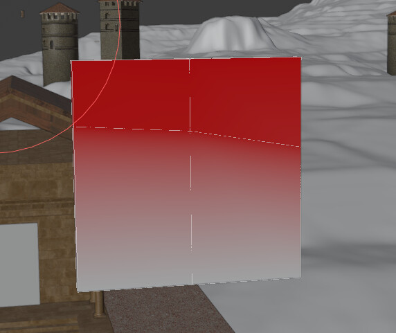
I have added a loop cut both vertically and horizontally, and added vertex painting:
As you can see there transition is not sharp, and for realism it does not make sense.
Could you tell me how should I create the mask with the shape of the sandstsone blocks? Should the white spots of the mask be the blocks that I want to replace with the other texture and the black ones the blocks I want to keep? And also how to connect it? I’ll try what the other user @blender.bruno has said for starters.
PD: I cannot attach more than one embedded image in one post since I’m new, so I’ll add more posts with the images.
Yes, basically. The more vertices you have, the more fine-grained you can paint. Usually, the added geometry is worth the costs, especially nowadays that geometry usually isn’t the main performance problem. Of course, you will always need to strike a balance.
Since you want to do it in UE anyways, have a look at this tutorial. He explains the process of modulating the vertex paint gradient (which, as you said, is a mask) with another mask.
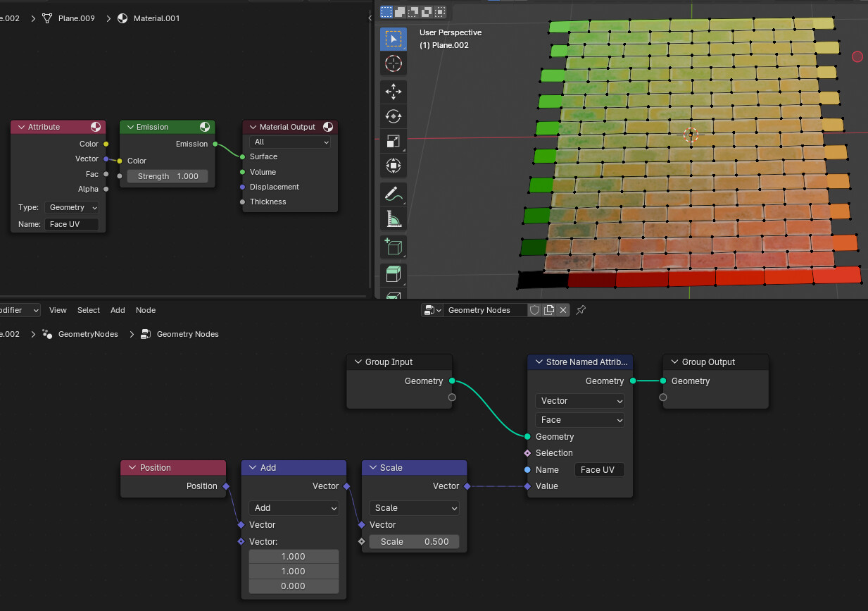
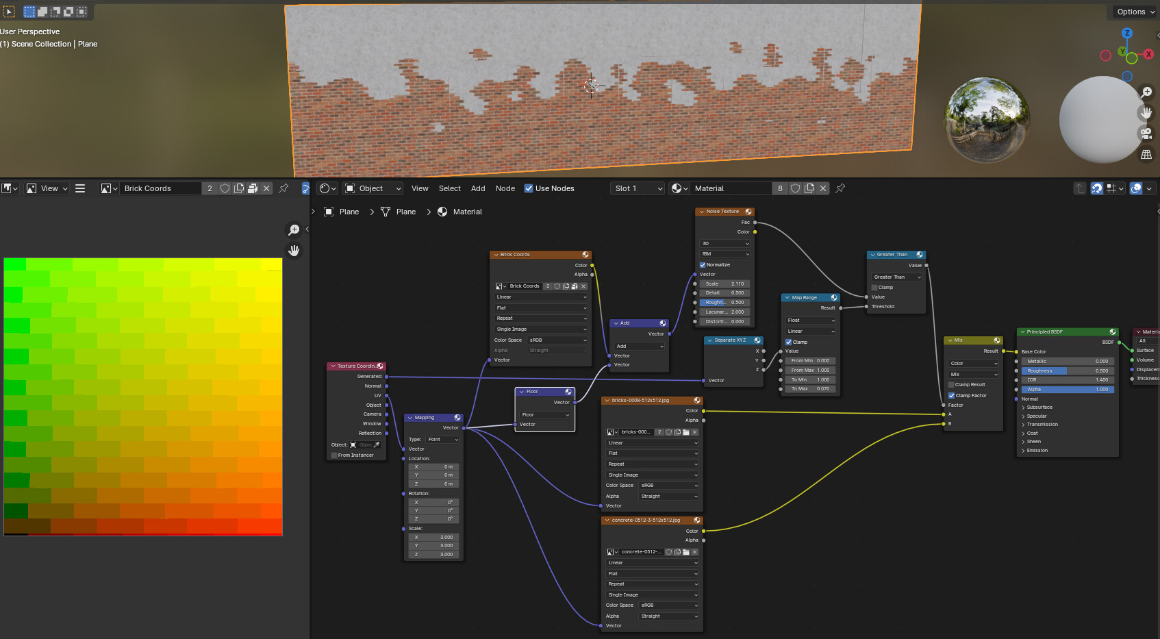
I created a rough mesh that follows a reference 2*2 plane with the brick texture and added the following material/GN combo to create a brick coord basis using emissive bake.
You could use the procedural brick texture within Blender, overlay it on top of your sandstone blocks with a low opacity, and dial in the right size. Then you can fill out the blocks with either black or white, depending on where you would want the different materials to show.
I would probably do it in Substance Designer, but ofc not everyone is access to it and it may be a bit overkill to learn another software just for the mask.
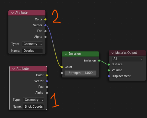
It surely is a mistake from my part. Maybe because for “Brick coords” I am using the same albedo of the sandstone bricks that I am using in the mix node? Or maybe a UV problem?
The blocks do not have a regular shape, a procedural brick texture would be hard to match with the sandstone. Also, if I need to mask only some blocks I find it easier to just create a mask in GIMP. As for the mask, would something like this do?
I’ll check that video you sent tomorrow. Firstly, I would like to set the material in Blender before UE to check if it looks good, only because I don’t want to go back and forth importing and exporting models until they do look good.
My textures aren’t procedural either… The whole point of making the coordinate texture “Brick Coords” manually is because the brick texture is not procedural!
Looking at your network it is clear that you didn’t understand my suggestion at all.
Apologies if I didn’t explain myself properly. I’ll try again.
The 1st image in the previous post shows a mesh which is tracing the source seamless brick texture (it is a non-procedural seamless texture with irregular brick shapes) such that each brick gets a mesh face. The edge faces get duplicated and translated by x2 or y2 to overlap the edges since the reference texture is seamless.
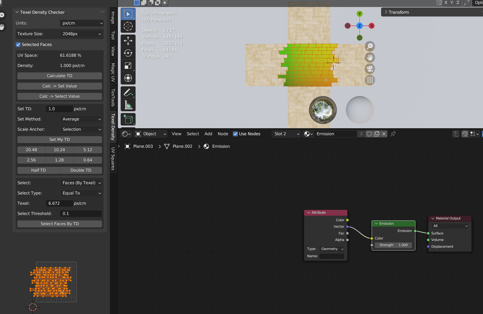
The faces are then colored using Geometry Nodes (shown in 1st image in the previous post). The result of that is baked onto a 2x2 plane (which is located just below the brick mesh):
That resultant baked texture, “Brick Coords”, is shown in the 2nd image in the previous post and that is used to dynamically create the mask via a noise texture.
Here I’m using an Empty to demonstrate the utility of this method.
Hopefully it made more sense this time. If you don’t understand anything, please ask questions.
Extra details...
You can use GN to sample the Empty’s approximate UV which will then allow you to use the brick coords directly to not get banding… but I think that is a separate topic maybe and don’t want to overwhelm the reader so this info is an optional extra.
Well I am starting to understand but I have two questions:
1- How to create the mesh that follows the brick pattern? Do I just manually create faces on top of each block in the texture map? Here is the one I did on a 2x2 plane (tiled in X and Y, so to make the edge blocks).
I’m pretty sure I have a UV problem, since the rows of blocks in the UV map are not aligned like in the texture. Also, this happens because each face is disconnected geometry. Should I connect them instead? I should subdivide each horizontal edge so to connect them.
2- I need to move all the texturing to UE afterwards, will this be able to be recreated in engine?
Yes… some manual work is required to line up the faces with the bricks. See example.
Additionally the GN operates on a 6*6 grid so the mesh tiling happens automatically. Edge-overlap is taken into account also so there are no more discontinuities caused by the UV “floor”.
You should be able bake for unreal or alternatively to build similar shaders in Unreal since math is math is math is math.
Should the vertices of each brick be connected or not in the “Brick Mesh”? In the image below each brick is disconnected. THe UVs are misplaced but when I had everything connected the GN also gave me a lot of light (in that case blue).
I have tested that changing the origin of the mesh makes the light intensity and color change too.
ALso when I bake the texture to a 2x2 plane, the resulting image is just all black. So, something is wrong too. But I used your configuration from before: select brick mesh first, then the plane without texture, and run the bake command:
Doesn’t matter. I did both. In my example file you’ll see I mix in the default UVs in the gaps.
The source mesh should be at the origin on the xy pane and you won’t get any blue.
Source mesh UVs are irrelevant. We’re using the face coordinates for baking only. Target mesh should just be the default plane with default UVs.
Oh… Yeah, it sounds like you need to do some baking tutorials. Lots of steps you’re skipping on. Like making and selecting the target texture.
You can use my example as a template for the setup/configuration - everything in the xy plane, target mesh z at 0.001. Normals pointing up. Target mesh with target textures, etc.
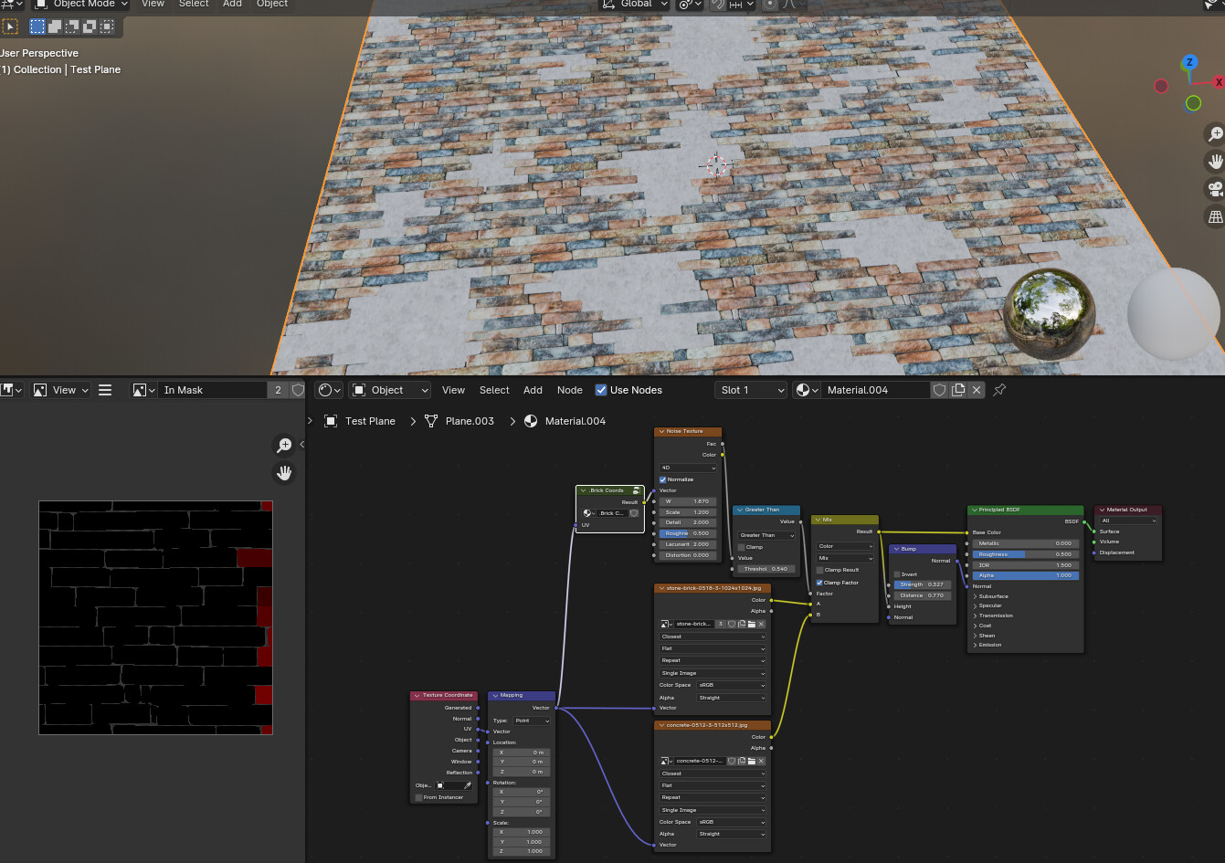
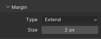
There are some yellow lines in the grey stone texture, I guess this is a problem of the mask. Upon closer inspection it shows some geometric shapes, which makes me think it’s not only the mask image (the coords) but rather the margin that I used in the bake:
The sandstone blocks should be at the bottom only, like you showed in your first post here. But if I exceed the 0-1 UV space or I scale the texture in the Mapping Node (like the first screenshot) it does not stay at the bottom. My take is that this has something to do with how the factor of the mix node is calculated. But I can’t identify what exactly. Maybe it could also be the coord mask?
If I used the other technique you have showed using the Empty as reference position, would that have any performance downfall at runtime?
Hi… please have a look at my example file. All the baking configurations are there.
Everything is in the disabled Collection called “Sources”. Enable it and have a look around.
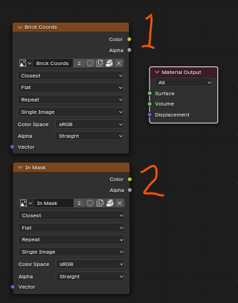
The material setup has a node-group that uses “Brick Coords” Attribute baked to the “Brick Coords” Texture, and the “Overlap” attribute baked to the “In Mask” texture (sorry it was WIP naming that kinda stuck, feel free to name them the same.).
Together they are used in the Node Group “.Brick Coords”:
to give seamless coords.
They work together to calculate the overlap so there are no lines where the coords are rounded down (i.e. floored).
As for the empty reference - that will just be part of the shader calculation with very little overhead if properly implemented. My example was merely for demonstration though - if you want to implement it properly it would be better to sample the nearest UV in GN , store that as an attribute and find the distance between that and the brick coords, map-range that and then use that to drive your mix (in addition to the noise).