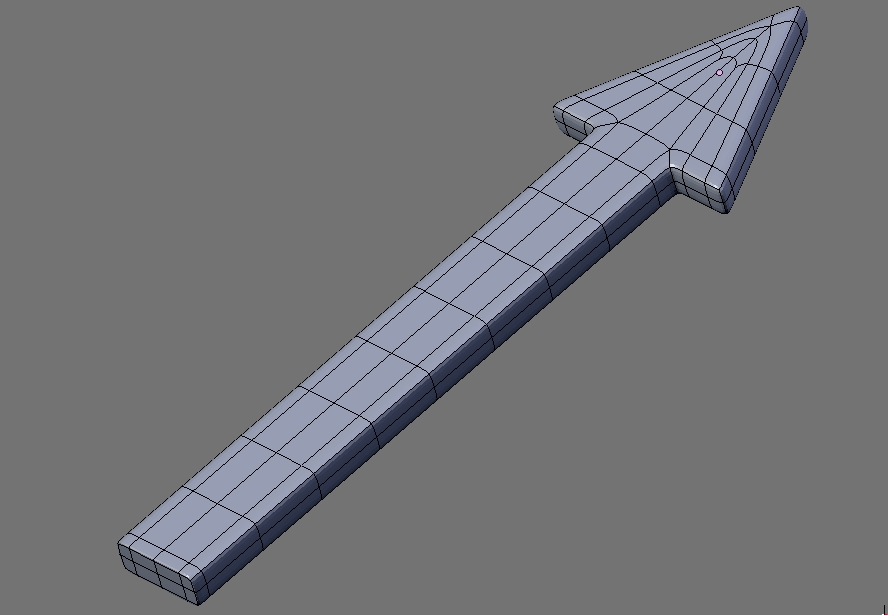
In my “3D diagram”, I want to draw a flat arrow that shows how an object is being rotated. So imagine a flat arrow, then roll it around a cylinder to make it curved. When viewed in the plane, it will look like an elongated rectangle with a triangle glued to the short end. From the side, after curving, it will look like the letter C.
Now, this should be a simple task, right? But I cannot figure out how to do it.
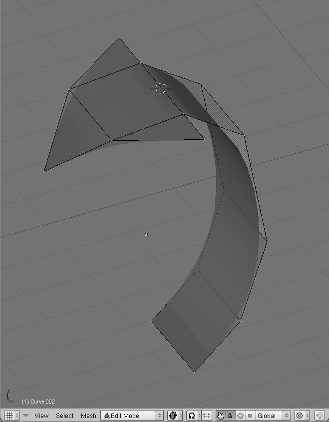
I tried subsurf, because that’s what I know best. However I’m having trouble with the arrowhead. To make the sides of the arrowhead pointy, I need to crease the edges. But this will also make a sharp corner where the arrow’s “shaft” meets the “point”, and that is not what I want. See the attached image, where I put the 3D cursor on the overly sharp edge.
I also tried a Bezier curve, which works fine as long as I work in the plane, but when I want to curve it I need to switch on the 3D option in the Curve and Surface panel, and the curve is no longer filled.
Finally I tried NURBS but I couldn’t figure out how to extrude the sides of the square NURBS plane to create the topology I wanted. In any case, from what I read on the web and in these forums, NURBS in Blender are not very usable at the moment.
Is there another approach that I’m overlooking? Is there a way to make any of these do what I want?
That is a cool technique. I love this aspect of Blender. The only problem of course is that unless you have a good number of segments you’ll see stepping on the curve of the arrow. The same technique could work on a subsurf mesh with smooth results so no reason not to use both.
That curve modifier solves it! I didn’t even know of its existence… Now I can just subsurf, and have the modifier deform after that. Even better, if I want to change the direction of the arrow I can just change the curve. Wonderful! Thanks a million!