You know what, you are right. I have no idea what crazy pig bit me there.
Might be because I am sick but it was a brainfart…
Boy how did I ever had the idea to seperate camera rays and mirror rays.
I also messed up the renderslots ystd. that´s why I always had the same render no matter the size of the outer sphere.
The question though is, if there is a right or wrong size. In real life you also can´t control how far or how near objects are to the sphere.
For specular reflection, the angle of incidence is the same as the emergent angle, which are cut in half by the normal
So yeh, your last figure is the shit. But this would mean that also real life lightprobes capture almost 360°, capture something though depending on the sphere´s size and the cameras aperture.
I remove my false figures, before someone thinks they are right, or even reuses them
I actually did some looking into it, and it´s quite hard to find information, but it seems a proper angular map holds 360° information in all directions, which is rather odd. I can´t really grasp or picture the concept behind it. Generally you take images of your mirrorball from the same distance and let a software stitch it to a angular map/lightprobe thus removing the camera on the image and stitching to 360°.
Now I want to know the theory behind it.
Seems I fell for the misconception that it only holds 180° which was foolish enough, b/c if it would only take one image you´d always have your camera on the lightprobe
Light probe images are created by taking two pictures of a mirrored ball at ninety degrees of separation and assembling the two radiance maps into one registered dataset. The coordinate mapping of these images is such that the center of the image is straight forward, the circumference of the image is straight backwards, and the horizontal line through the center linearly maps azimuthal angle to pixel coordinate. Thus, if we consider the images to be normalized to have coordinates u=[-1,1], v=[-1,1], we have theta=atan2(v,u), phi=pisqrt(uu+vv). The unit vector pointing in the corresponding direction is obtained by rotating (0,0,-1) by phi degrees around the y (up) axis and then theta degrees around the -z (forward) axis. If for a direction vector in the world (Dx, Dy, Dz), the corresponding (u,v) coordinate in the light probe image is (Dxr,Dy*r) where r=(1/pi)*acos(Dz)/sqrt(Dx^2 + Dy^2).
I´ll look further into it, this is quite inresting. If I got time I´ll code a bit. Should not be too hard to write an converter from planer spherical maps to angular maps.
HDRshop is not for commercial usage in the free and educational version, and the big one is 400USD. I think a free tool to convert spherical maps into angular maps would be a nice addition although it would be better if blender would support spherical maps, and two of them, one for background one for IBL.
Actually I win I rectified my false presumptions and learned something.
And I already figured it out Had to draw it though to be sure. Quite odd to map a point to a circle
Also, I don’t get what those images illustrate.
I can see the first image is a equirectangular projection, and the second is the same mapped to a sphere.
What’s the third one about?
EDIT: OK, so that’s the angular map. Is that just an illustration, or was there some mathematics involved? (looks like gnuplot though)
Thanks, fixed.
Also forgot the yellow and cyan dots in the angular map. Fixed too.
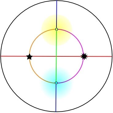
Third one is the angular map. The outer black circle is the black dot from the middle image, the center is the front from the sphere. Thats the illustration of the theoretical crap I posted earlier.
EDIT: You can´t edit while I edit the edit
No, its just Inkscape not GNUPlot.
This is getting out of control. However I am always eager to get some additional “input”.
I made a small addition to your angular mapping sketch:
The highlighted areas should be the areas where the least information is collected through the two virtual (or real) lenses.
Here comes my 50ct-question:
What is the advantage of using these equirectangular maps ?
The areas with the least density and therefore the least count of camera pixels are occupying a significant space on the map. And the outer edge of the projection is a infinitive small dot in reality. A solution could be to make two additional shots where the yellow and cyan dots are centered and use this data to fill in the information-gap.
P.S. @ GodOfBigThings:
Many thanks for the flowers to you and your 198 different personalities
The highlighted areas are not really areas with the least information. The yellow dot for instance, is, if you imagine the photograph of the mirrorball, the topmost last visible point. It is just streched out along the yellow line in the spherical map.
The whole yellow line in the spherical map is the same pixel, the topmost of the photograph of the sphere, thus in the angular map, it holds as much information as it holds in real life.
Same goes with the black circle in the angular map. It is the backside point of the sphere, one pixel flattened out to a circle.
I am not certain what algorithm is used to map a spherical map to an angular map, but it has to involve some sampling, nearest neighbour, or gaussian, or cube, or tent… depending on what is used, you´d loose some information due to sampling in the inner circle of the angular map, and “invent” some new information for the outer ring of the angular map. It is also possible that the inner and outer section, meaning the front hemisphere and the backhemisphere are sampled into the circular shape, so there is no loss of information, so that all segments hold the same amount of pixels, which would make sense to me, still the further out you get, the more pixels hold the same information.
All in all I find angular maps not very intresting. They seem to stretch a lot more than spherical maps, they are a waste of space because 21% of the image simply holds no information at all, many pixels hold duplicate information, due to the circular shape, most renderers use spherical maps only, and even with highres angular maps, the background never really looks nice.
But I guess cycles will replace BI, and be capable of spherical maps.
Uhm, that´s no angular map, thats how you create lightprobes to create an angular map, which no one really does, because everyone does spherical maps because they are better.
And that is really how pretty much everyone is doing it, either with this gardenthingies, ball bearing balls, or styrofoam balls, plastered and painted with highly reflective pain…
However, by now this thread is about how to map the gathered information properly Or in other words, every fool can take an image of a shiny ball, but if you DIY, how would you map the taken image into a texturemap?
Thanks for everyone for the interesting discussion on the topic! Allthough I have to admit some of it is a bit above my head
After all this discussion, is there a workflow that someone could recommend for making a hand painted background for my world? It’s an animation so it needs to be some kind of a map, but I’m not sure whether I should try to make a spherical map or an angular map.
It would be great if some one could suggest what to do after I have painted a rectangular painting in Photoshop (in order to create a proper world background out of it)!
The answer is quite easy. Unless you need your background to be mirrored or you use it for IBL drop the idea of an spherical or angular worldmap. Just use a backdrop, either a simple plane, or a cylinder, maybe even a sky hemisphere with your texture on it as world.
Else there is no way to create a full spherical or angular map out of a rectangular non repeating image.
If you want it as angular map, I only see one way to make it pretty much perfect.
Create a cube with a cubemap, do your best to paint or wrap your texture on the inside of it, just like a environmental cubemap texture.
After that, create a grid, unwrap it, and use the warp tool to make it a sphere. Place the sphere in the center of the cube and make it a mirror material. After that, bake the cubemap on the sphere´s grid texture.
Now you got a spherical map. Now take the spherical map into a tool that can convert spherical to angular maps.
The alternative is to just map your image to one side of the cube and do the same baking. It will give you a spherical map that will project correctly, however it will be black for the most part because your image only covers one face of the cube.
If you take your image, and are able to map it to 3 sides of the cube, fill the 4th side with blenders texture paint so it is seamless, fill the top with blue for a random sky and the ground with green fro random grass and bake it.
If the final animation mostly has horizontal movement, no one will see the missing top and bottom, however it will cast light in the color if you use IBL.
As arexma stated, forget about the lightmapping cr… As you want to paint your background, the fastest way is to map your background to the inside of an open tube,
This tube should enclose your complete scene as well as the camera of course. The seam of the background image should be on the opposite side of the camera lens to allow some modest camera & lens movement. The normals, which are defining on which surface Blender shall “paint” to should point to the inside of the tube, as this is an interior decoration job.
And you have to take care of the sky and floor as well. If it is an outside scene a plane for the floor and a sky dome enclosing the tube with some clouds will do. Then you can paint your background image leaving the sky portion transparent.
For interior scenes a UV-mapped cube would be better suited. You have to paint the six different views like you would design a carton box. Then pin them to the inside of the box representing the walls. The problem areas with this projection type are the edges of the box, which is a quite perfect mapping situation for modeling rooms.
And just in case you haven’t met it before:
IBL stands for Image Based Lighting
Also, FYI, I was in the bookstore last night and 3DWorld Magazine, issue 144 has about a 4 page instruction / article on creating your one angular, lat/lon, cross etc maps. They also give resources where you can buy them for around $15 or 10E each.
Yes, it covers the theory of map creation and talks of the simple to complex variety ways of creating them.
It talks about creating panorama shots with camera, tripod, photo stitching them together with different programs, then creating the maps with other programs.
It also talks about creating your own from virtual landscapes such as VUE, and exporting them into Photoshop to create maps there.
The other programs are pretty specific, but I do remember one solid one comes from Paul Debevek, who could could be called the father of angular probes.
I don’t have the issue, no.
It basically says : “Take a chrome ball, shoot it, plug it in $100 software”
If you set some angular maps from paul debevec’s website as world texture in blender, even they have some distortions.
But those distortions don’t matter for IBL, as they still roughly resemble the surroundings. And since this light probe thing was mostly done for IBL, I guess the goal when shooting in real life is just to get as close as possible.
The dutch skies series are some of the best HDR panoramas. Bob Groothius offered me a free DVD. Too bad I couldn’t even afford the $10 shipping cost. :mad:
I have learned a few things recently that I’d like to share. They might help people struggling with the same issue in future:
When you shoot a reflective ball with a camera, you don’t get an angular map.
An angular map is a different projection that was made (probably) because there is too little detail around the edges in a photographed reflective ball.
Angular maps seem to be linear, meaning distance from center in angular map is directly proportional to angle subtended in an equirectangular projection. (though I’m not sure, I only did rough measurements in photoshop).
Nevertheless, Luminance HDR, earlier known as qtpfsgui, is an open source program that can convert between equirectangular, angular and “mirrorball” panoramas.
To convert, go to Edit->Projective transformation. (this can take a few minutes with large files)
As mentioned before, “mirrorballs” have very little detail around the edges, and are unusable for anything other than IBL. (and of course converting them doesn’t solve this problem)
But angular maps, surprisingly to me, have very little distortions and are even better then equirectangular panoramas, since they have artifacts (very little) at only one point, compared to two for an equirectangular panoramas.
Until blender supports equirectangular panoramas, this will be my way of using equirectagular images/HDRs in blender.
Thanks for sharing. It has been a very interesting thread, hasn’t it?
My idea of an angular map is that you can define for any (infinitely small) vertex one mapping point based on the angle of attack of its normals. As you can practically see normals only that are pointing to the camera this leaves you with a hemisphere , the vertex being the center point.
On an two dimensional map there is one point for any given x and y . The larger the map is, the higher the resulution of the resulting image. The alternative method is giving an angle and a length (Rho/Theta)
On an angular map you can point at a specific point on the map for any given angle of attack of the vertex normal.
From the vertex point of view a flat grid projection would be distorted because the angles are not isolated from the length information, as the length to the grid center would differ from the length of any 45° angle. But if you use a material pinned to a hemisphere the length component information will be eliminated and one can point to a specific spot on the hemisphere for any given angle of attack. The larger the hemisphere is, the larger the resolution would be.