How to crumble an object from the top to the bottom

I have fractured an object now I want it to crumble based on a influencing object.
Think of a diving board, I want it to start crumbling from the tip to the base. Or a tall building that crumbles from the top to the bottom.

Is there a way to do this in Blender?

You may look at this

or that

to see how to control the destruction area by another object.

( Had some other ref… but can not find it now :sweat_smile: )

These demos you linked above only show how to break up a surface laying flat, all the fractured objects are contained in a shape that holds them in a horizontal flat position until the colliding object intersects. What I am looking for is a way to have an object crumble from the bottom up. Think of a stalactite hanging from he ceiling of a cave, and it crumbles from the tip to the base.

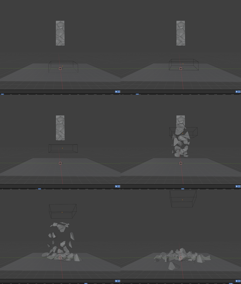
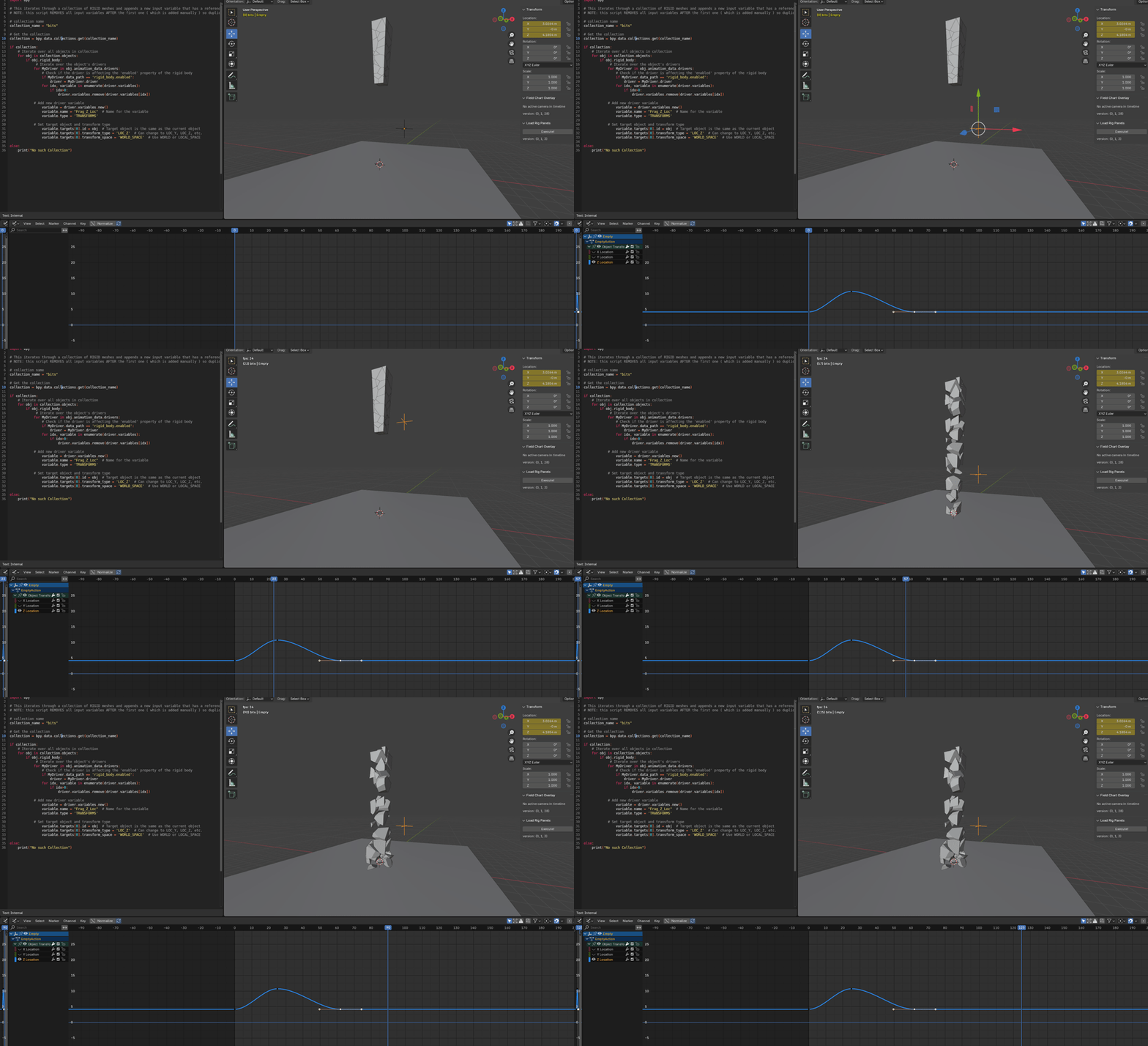
Here is a simple example of what I am trying to do with fractured active bodies.
NOTE: To demonstrate what I am trying to do, in this example I baked out the action of all pieces falling at once, then offset their time in the dope sheet, The wire frame collision box is not a collision box it is just a cube shape switched to wireframe. I did this so I could demonstrate what I am trying to achieve.

Any ideas how to achieve this in Blender?

ActiveBodies_activated by influence object.

To be honest in the past i did watch such tutorials with great interest but my old computer was by far not powerfull enough to re-search this in depth.
I allways assumed that those control by some other object also is able to crumble not only geomtetry “at lower level” but also some “above it” and the controlling object can also go up and to what you are searching for… so i have another thing to try out with my newer computer :wink:

Anyway the “trick” you came upo with is also interesting.

Something like this maybe?

explode_example.blend (1.0 MB)

This is a quick, down & dirty example. Yes, it crumbles from the bottom to the top.

Subdivided a cube a couple of times, giving me 96 faces. Added particle system with 96 particles. Added explode modifier. Run the sim and 96 faces randomly fall away.

To control the particle system to start at the bottom, I added a texture to the particle system. I used a ‘blend’ type texture, see texture panel in particle system. It gave me a gradient that is black at bottom, white at top. In front view of cube, I unwrapped it using Project from View. The texture is what controls the emission of particles. Black at bottom = first emission of particles.

Hope you can adapt this to your needs,
Randy

Thanks. I am not entirely sure if this will do what I need, I will have to play with it a bit. Thank you for the idea.

Sorry, I don’t think my idea will work for you. Your example animation shows large chunks falling. My idea would work if the object is disintegrating into very small pieces, like sand. For larger chunks like you show, it won’t work.

What’s wrong with doing it the way your example shows?

Randy

I could do it the way may example shows, but that is baked and then the keys are offset. so it is not a real simulation, it might have to do.

I am surprised Blender doesn’t have an easy way to do this with active rigid bodies.

@Jettam

Hi,

It is possible :-

but there’s a REALLY annoying restriction in setting up a driver to do this. If you’re familiar with adding drivers [ and using CTR-L to copy animation data to multiple rigid bodies ] and how to run a script, then I’m happy to elaborate.

The script is necessary to automate the addition of a new variable to the driver … which the annoying restriction prevents from being an elegant solution. :roll_eyes: ho hum.

Unfortunately, I don’t consider this is a ‘simple’ solution. It will need explaining, so appending my Blend file here will not help either as the order of proceedures to get it to work in your own files is not evident in my file.

Let me know,
Cheers,
Dj

Yes I would love to know what the process is to do this. I will try to replicate it this week.

Thank you

I am familiar with CTRL L to copy a Im data and I know how to run scripts, I can’t write scripts though.

Okay, no problem.

PART 1
( Jeepers, this is going to be a long post, so I’ve broken it into separate replies) :open_mouth:

Here we go . . .

As you already know how to set up a rigid body system I’ll assume you have something similar to this where every mesh has the rigidbody physics on it:

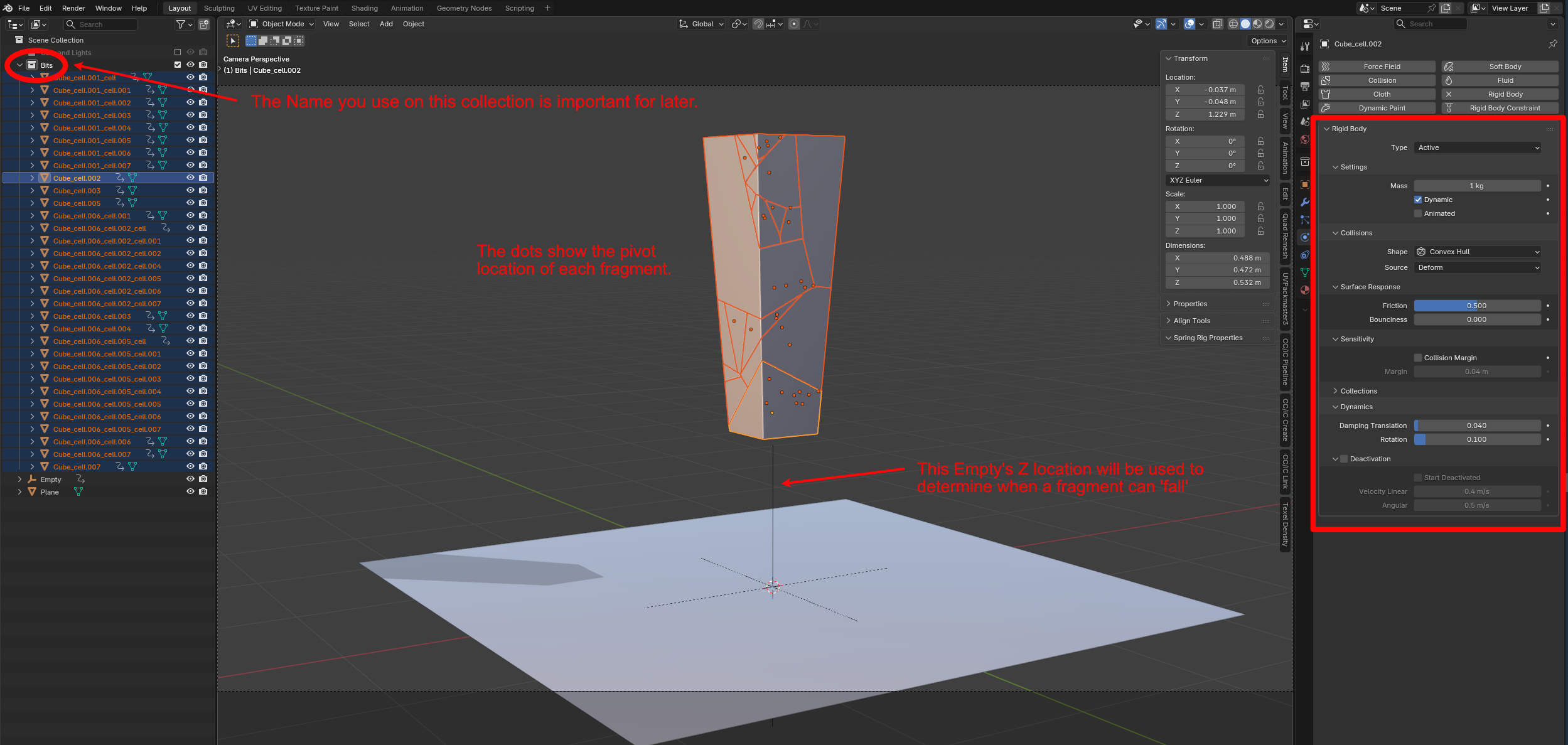
Place all the rigidbody meshes that are going to ‘fall’ into their own collection and name this collection. [ it’s called “Bits” in my file ]. You need this actual name later on for the script.

I’ve used an Empty to drive the effect. You can use any object that has a location transform.

In essence what this effect is going to do is compare the Z location of each fracture bit to the Z location of the Empty and if the Empty is ABOVE ( ie higher in value ) then turn ON the rigid body’s Dynamic toggle causing it to start simulating:

image

By animating the vertical position of the Empty you can control when this happens.

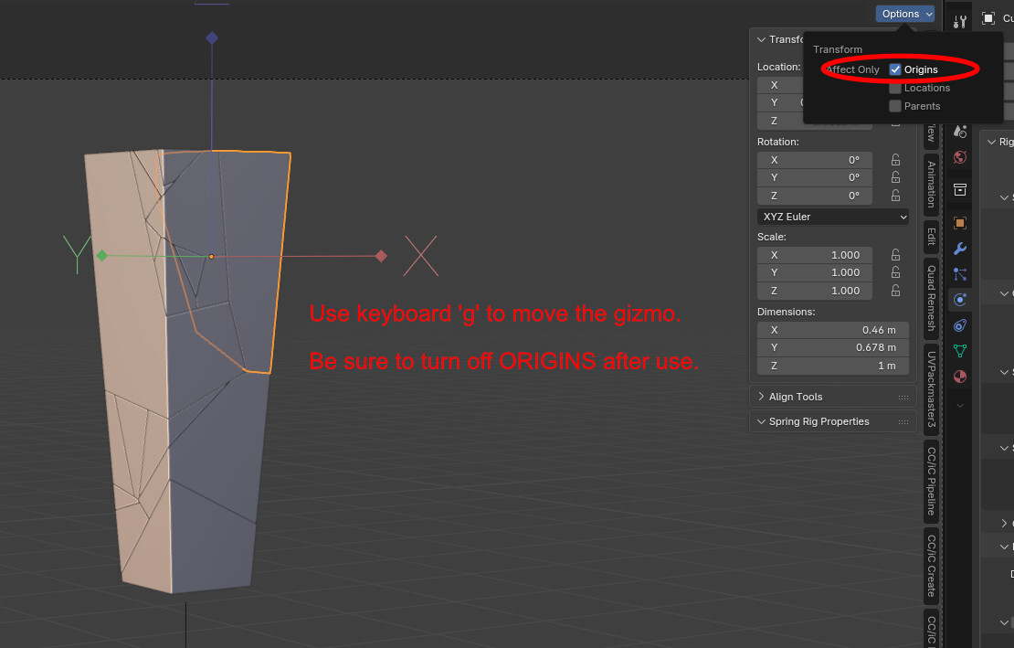
Note. The centre of each fragment is marked by the dot that appears when you select a fragment, this was created when you ran the Make Fracture effect on your origianl mesh. It is the location of this dot that is used in the calculation for the fragment bit’s location. You can manually move these centres . . .

You may want to do this to control specific fragments to fall in a certain order to art direct the effect.

Now we need to add a driver from the Empty to each fragment. Pick ONE of the fragments, this will become the Active mesh and will be the one we create the driver on.

( There are 2 ways to add a driver, I’m showing the more indirect method for clarity in what it’s doing)

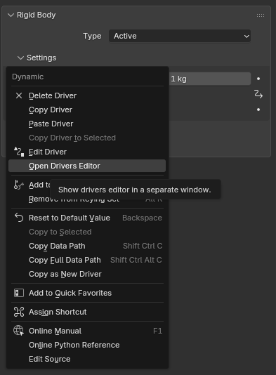
RIGHT click your mouse over this :

image

A dialogue box appears, pick Add Driver:

Another dialogue box will appear:

Ignore this, click anywhere and it will vanish. We now need to open the drivers window to edit it more easily. You can do this by creating another window panel or RIGHT Click again over the ‘Dynamic’ label and choose:

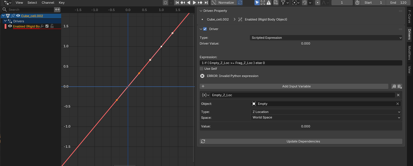
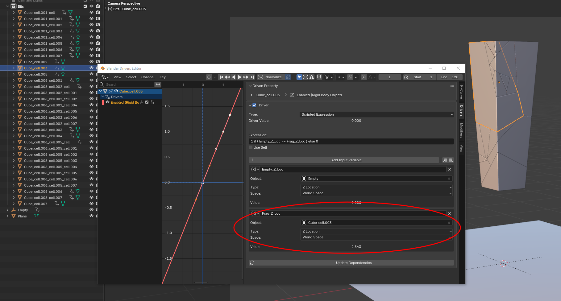
A floating panel appears and in here we fill in the drivers parameters. I’ve numbered them in the order to do them . . .

#1. Select this.

#2. From the drop down select Scripted expression

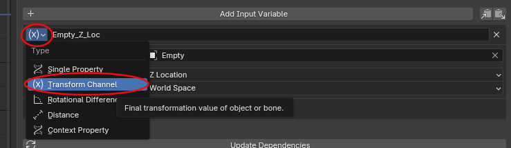
#3. click eye-dropper and select the Empty ( or whatever object you’re using to get a location ) in the viewport.

#4. Change this in the dropdown to Z Location. ( if you don’t see this option be sure to toggle here:

#5. Where it say “var” change this to “Empty_Z_Loc”. This is the name of the variable that holds the z value of the Empty, calculated on each frame of the animation.

#6. The Formula for the driver:

1 if ( Empty_Z_Loc >= Frag_Z_Loc ) else 0

copy and paste this line EXACTLY into the expression field. When you’re done it should look like this:

Now we need to copy this driver setup to all the other fragments. Select all the meshes then SHIFT-select the ACTIVE fragment last and using CTR-L link the Animation Data.

If you now pick any fragment it should show exactly the same driver in the driver window.

END OF PART 1.

PART 2.

The driver expression will not currently work, “Error. Invalid Python Expression”

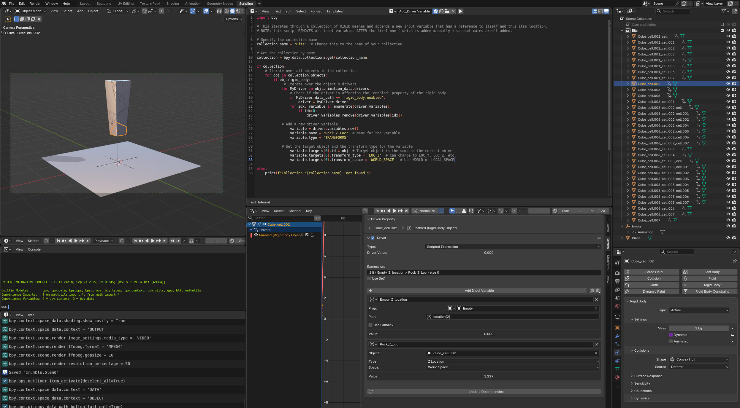
This is because the driver has another variable named “Frag_Z_Loc” in the formula and we’ve not told it what this is. It needs to be the location of the actual fragment that the driver is running on. This is obviously different for every piece, so we need to add another variable to the driver that explicitly gives it a reference to the unique mesh of each driver.

Ordinarily, and in any sane world, the use of “self” in the driver would do this. Unfortunately this is the REALLY annoying restriction that I alluded to in my first reply. Rigid Body meshes do not permit a reference to the self, either in the driver or a script. I have no idea why.

Scripting to the rescue. :smile:

The script will iterate over all the meshes in the COLLECTION of the rigid bodys and add another input variable that is unique to the object and makes the formula work.

Open a text editor window in one of your panels:

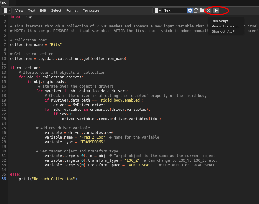
Click ‘New’ and paste this script into it:

import bpy

# This iterates through a collection of RIGID meshes and appends a new input variable that has a reference to itself and thus its location.
# NOTE: this script REMOVES all input variables AFTER the first one ( which is added manually ) so duplicates aren't added.

# collection name
collection_name = "Bits"

# Get the collection
collection = bpy.data.collections.get(collection_name)

if collection:
    # Iterate over all objects in collection
    for obj in collection.objects:
        if obj.rigid_body:
             # Iterate over the object's drivers
            for MyDriver in obj.animation_data.drivers:
                # Check if the driver is affecting the 'enabled' property of the rigid body
                if MyDriver.data_path == 'rigid_body.enabled':
                    driver = MyDriver.driver
                for idx, variable in enumerate(driver.variables):
                    if idx>0:
                        driver.variables.remove(driver.variables[idx])

            # Add new driver variable
                variable = driver.variables.new()
                variable.name = "Frag_Z_Loc"  # Name for the variable
                variable.type = 'TRANSFORMS'

            # Set target object and transform type
                variable.targets[0].id = obj  # Target object is the same as the current object
                variable.targets[0].transform_type = 'LOC_Z'  # Can change to LOC_Y, LOC_Z, etc.
                variable.targets[0].transform_space = 'WORLD_SPACE'  # Use WORLD or LOCAL_SPACE

else:
    print("No such Collection")

In the script where it says

collection_name = "Bits"

Replace Bits with the name of your collection.

You don’t need to have anything selected in the viewport, just press Run script:

And just like magic every rigidbody mesh will now have another variable that references it’s specific name and the formula will work ( the Error mesage will go ).

That’s it.
If you’re Empty is animated, as it moves above the fragments, when you simulate ( ie play the timeline ) the fragments should fall in ‘sequence’.

Yay.

Any questions, let me know.
Cheers,
Dj.

:exploding_head:

I had thought of this idea, using drivers to enable the rigid body sims. I knew setting up the drivers would be a task and I would have probably went in the wrong direction by trying to use a Distance type of driver. Using a script to create a second driver variable is another great idea! I’d have just manually added in the 2nd variable…

Thanks for sharing this!!

Randy

You’re welcome.

Without the use of a script this sort of set-up is just not feasible, expecially when there are hundreds of mehes, since you’d have to assign the second driver variable individually to every mesh. With the above script you can add as many meshes as you like, or rename them, then, so long as you first copy across the rigid body to any new meshes, then link the animatioon data and finally run the script, it will all update immediately for the next simulation

A quick re-render with a couple of hundred fragments:

Have fun.
Cheers,
Dj.

Thank you for laying all this out for me.

The issue I am having is if I animate the empty up and then down again the falling fractured pieces freeze.

rigidBodies_expression

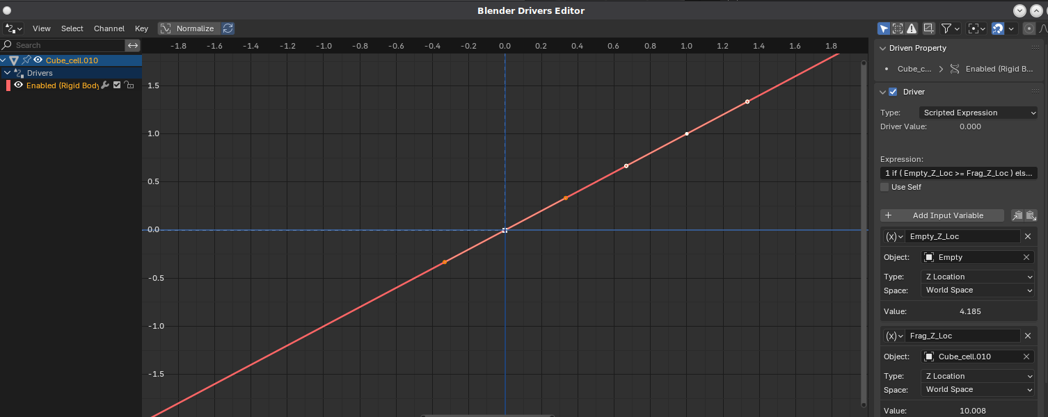
Here is the driver setup for one of the pieces:

It seems possible with that Addon.
But I haven’t really tried or reviewed it.
I also didn’t see what version of the blender this Addon would support.

However, this Addon was used for the collapse animation.
I used this Addon on blender 2.79, but it’s been forgotten since I haven’t had an update for a long time.

The latest update for this Addon was two weeks ago.

Hey there,

Yep, this is becasue of the way Physics bodies and drivers are mis-matched in the data they have access to.

Here’s why this happens . . .

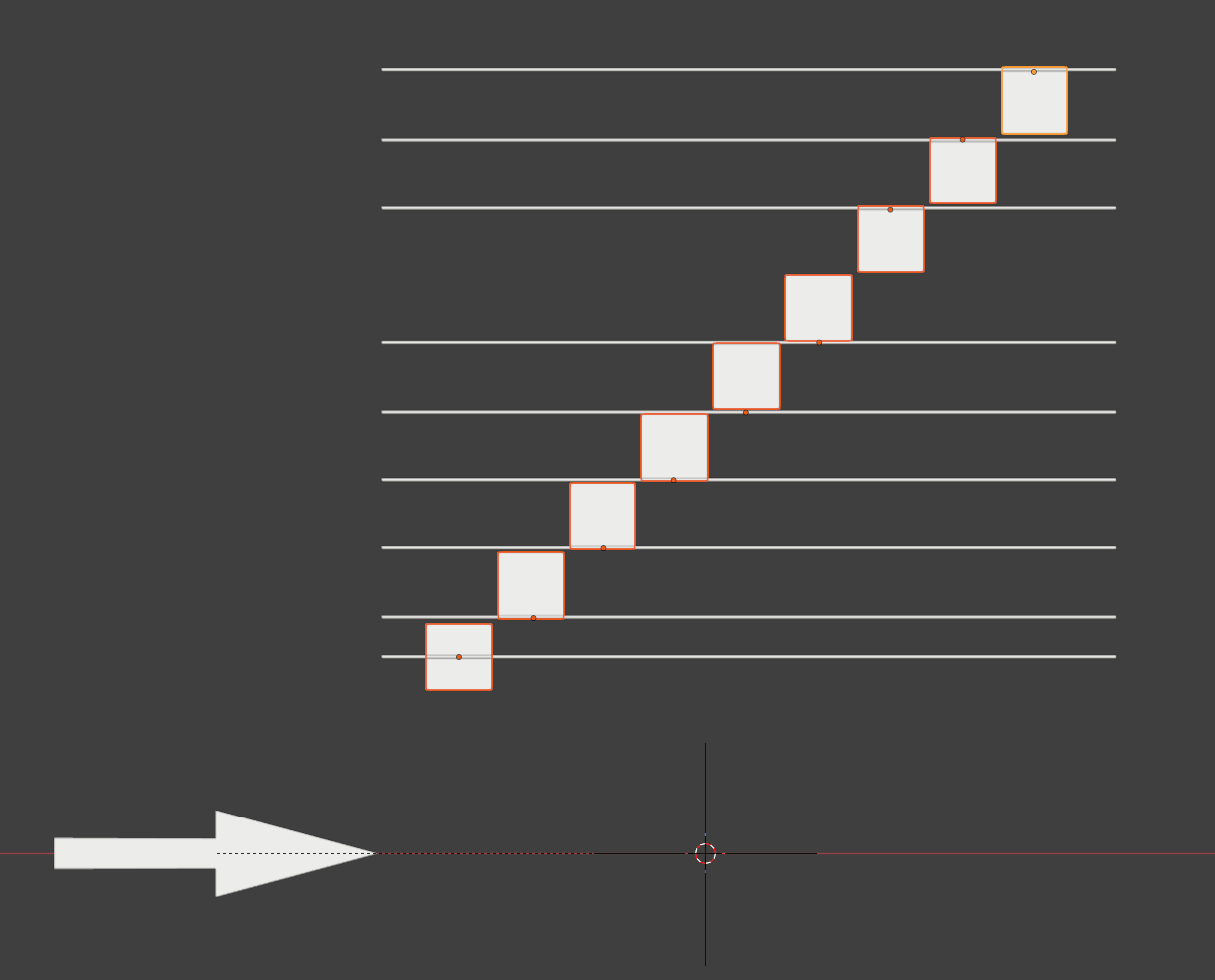
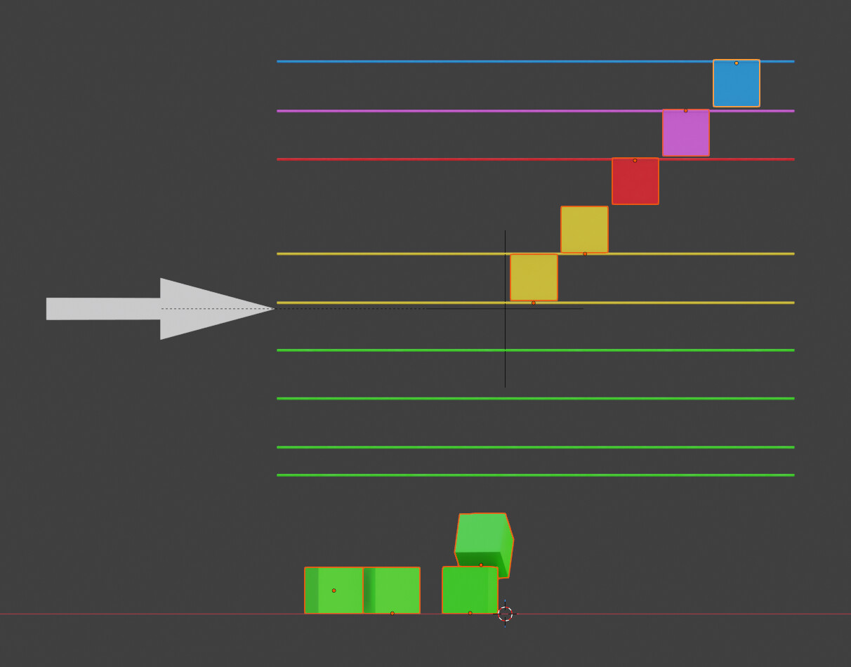
A basic setup with cubes …

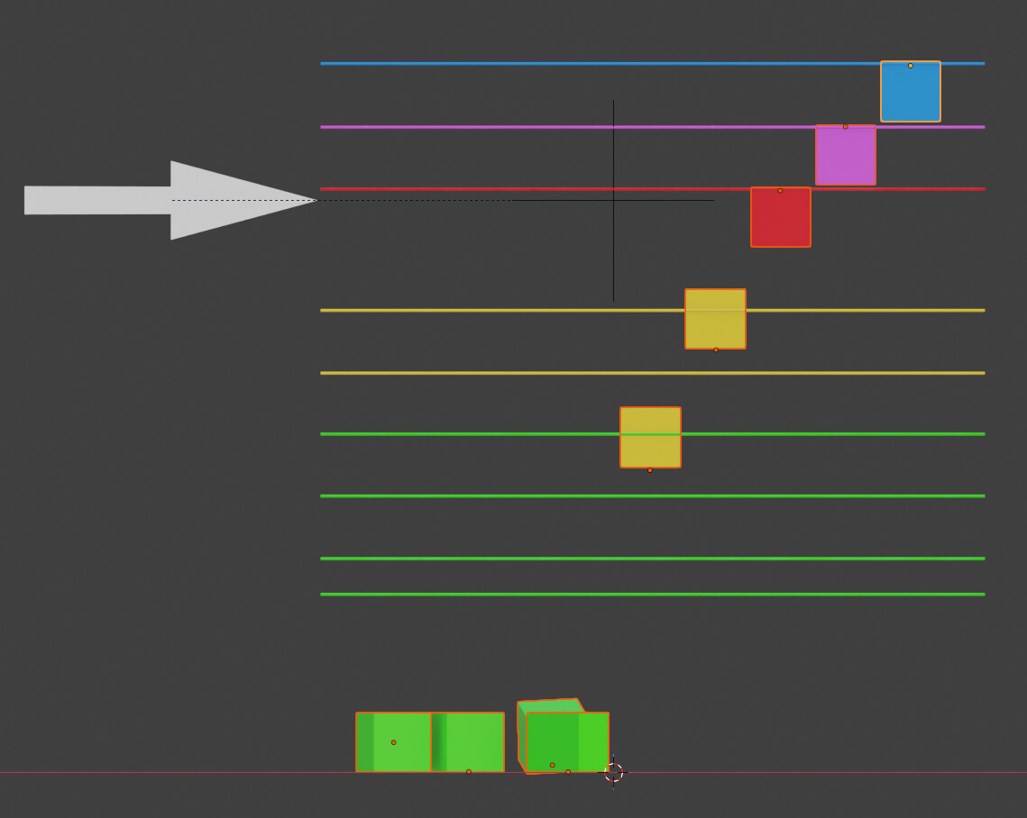
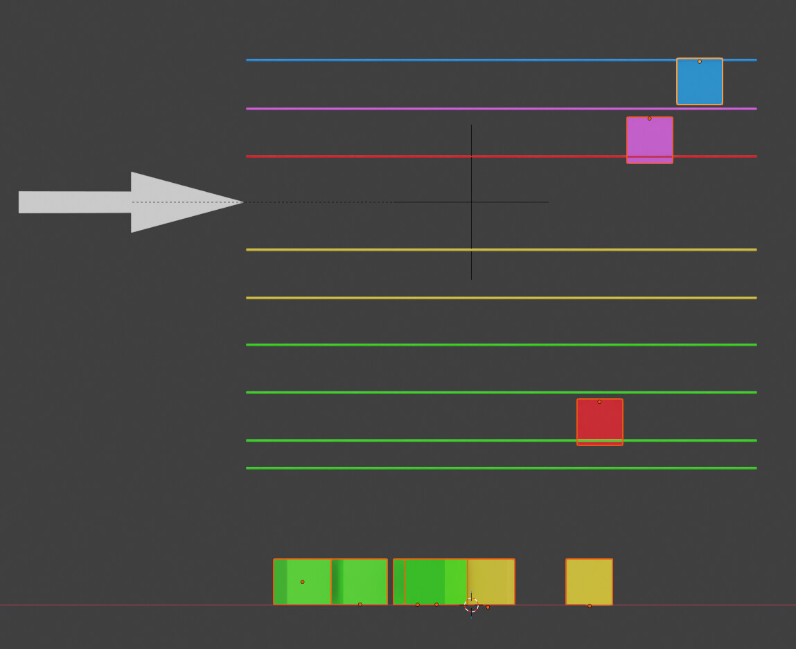
The horizontal lines show the point at which the center pivot point of each cube [ the little orange dots ] sits. Notice that I’ve deliberately offset these centers. I’ve colour coded the cubes and lines for clarity.

The arrow points to the height of the animated empty.

Simulated it does this . . . [ click and drag in the playback timeline to move back and forth ]

The arrow rises and all the green cubes fall ,

there’s a delay the arrow rises more and the yellow ones fall.

At the maximum height of the arrow the red and pink have started to fall…


However, the red and pink one stop falling when the arrow starts coming down again. The yellow ones keep moving until they naturally come to a stop.

The key thing to note is where the arrow is in relation to the line colour. A cube’s rigid body is in-active when the empty [ ie the arrow ] is below the line colour for that cube.

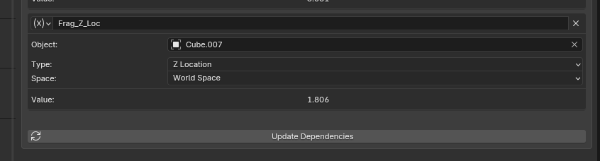
The actual position of the mesh [ being simulated by the physics engine ] is reported in the driver feedback . . .

here it’s the value 1.806. However, from my experiments, the driver only checks the start location, not it’s ‘true’ simulated location once a simulation has been initiated, so it then assumes the cube hasn’t moved. In fact if you drag the time line and look at the value on the driver after it has supposedly stopped falling, it jumps between the actual and original locations, and the dynamics state flickers between on and off across adjacent frames erratically.

Using drivers with a physics simulation is obviously a somewhat compromised affair. You might want to look into the add-on that Kim, [ @oo_1942 ] has marked in the previous post.

Other than that, sorry I can’t offer much more assistance without a specific idea of what you are hoping to achieve.

Cheers,
Dj.