using geometry nodes, I would like to distribute points on the surface of a plane with the important porperty that the point density increases gradually along a specified direction. This means: Having a less points on one side of the surface and more points on the other end, where the amount of points in-between changes gradually.
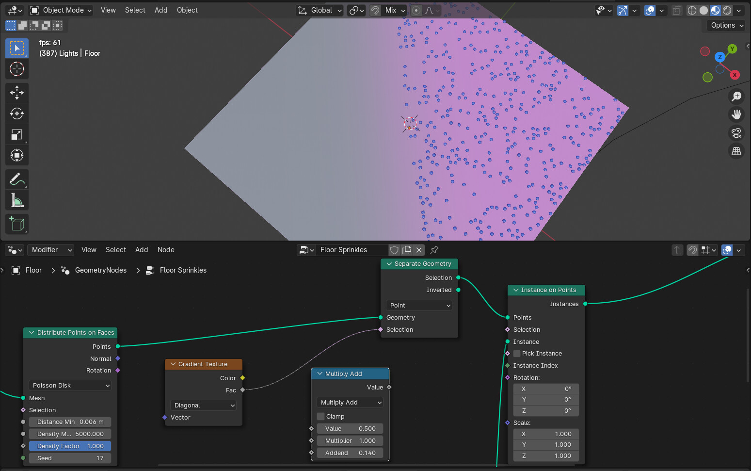
The best I’ve got so far is to combine the “Distribute Points on Faces” node with the “Separate Geometry” node, where the selection is determined by the “Gradient Texture” node. However, this will just threshold the points and not change their density.
If I furthermore put a math node like “multiply add” in-between the “Gradient Texture” and “Separate Geometry” node, I can basically influence where the selection starts and where it ends. However, this still does not change the density.
Also, the “Gradient Texture” node comes with the drawback that I just have a predefined set of gradient directions available, which makes it less flexible. I would like to be able to set that direction really arbitrarily.
For my main problem, the gradual point density, I suppose it might be a good approach to have a rather high density set via the “Distribute Points on Faces” node at first and then randomly (e.g., according to a uniform random distribution) select points for display (or, the other way around, select them for not being displayed) where the amount of selected points is proportional to the underlying gradient.
But, I’ve got no clue how I could achieve this. I don’t even know if I am overcomplicating things and whether there might be an even simpler solution.
Thanks in advance for your time and for any helpful hints!
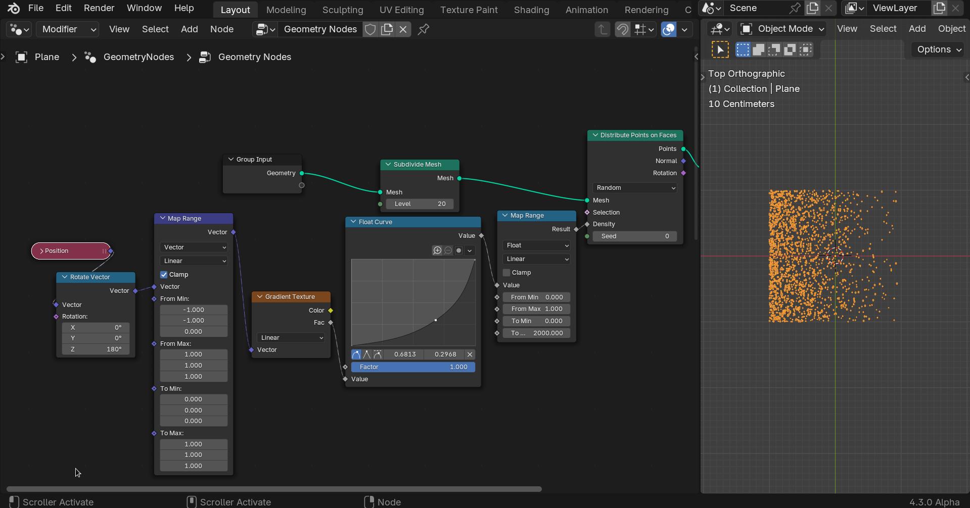
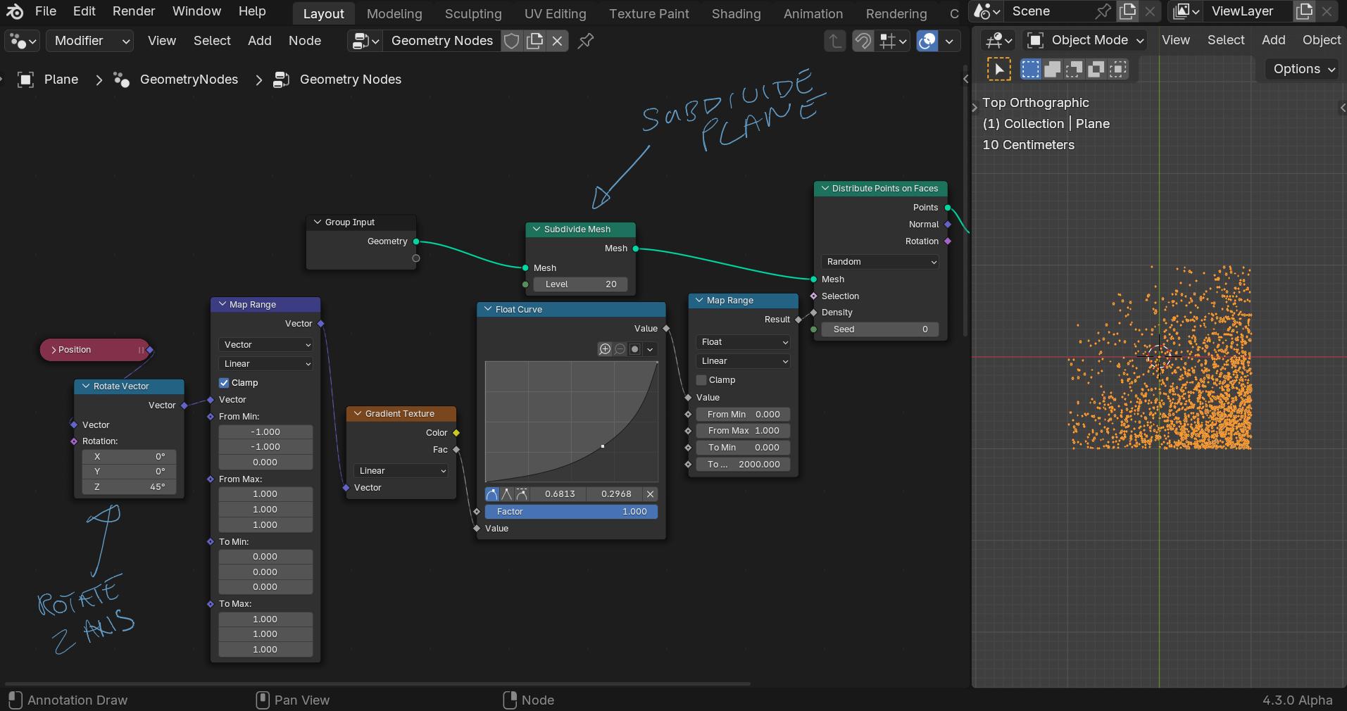
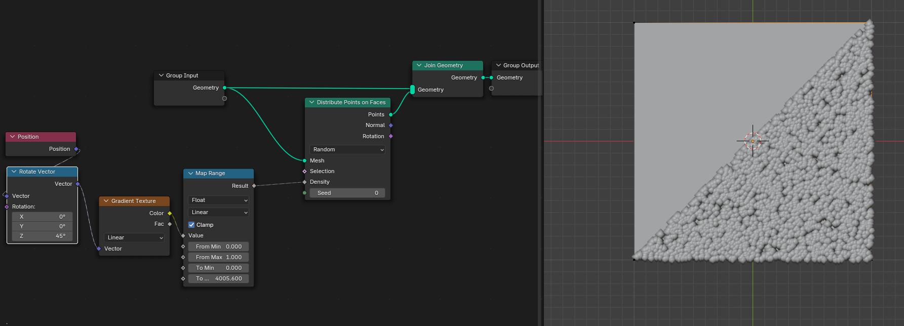
You need more faces than just one plane to map the gradient giving different values for each face. So you need to subdivide the plane a bit to get a gradient.
The float curve gives you a bit more control of the gradient.
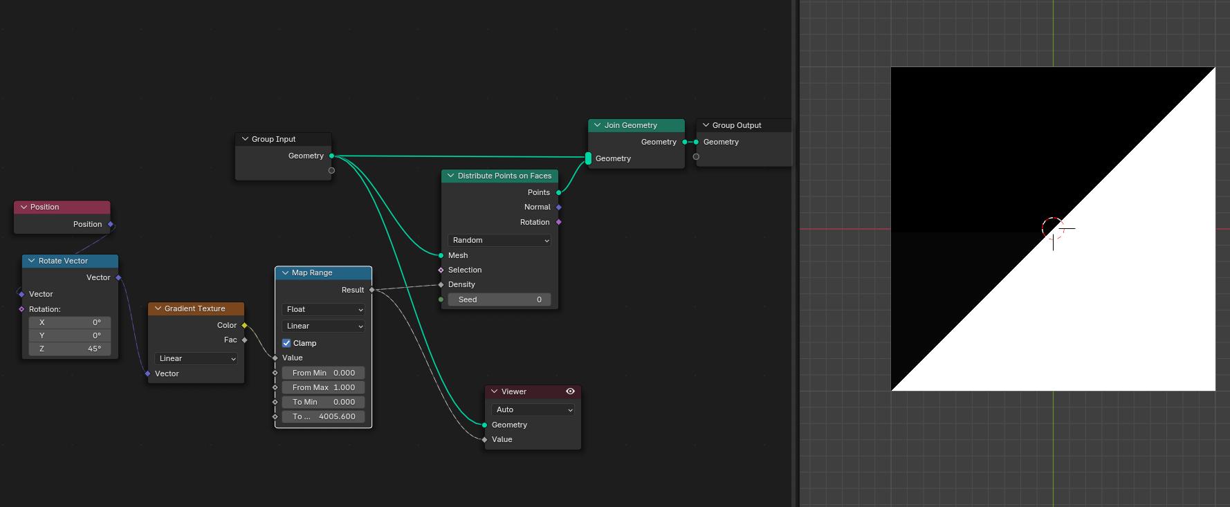
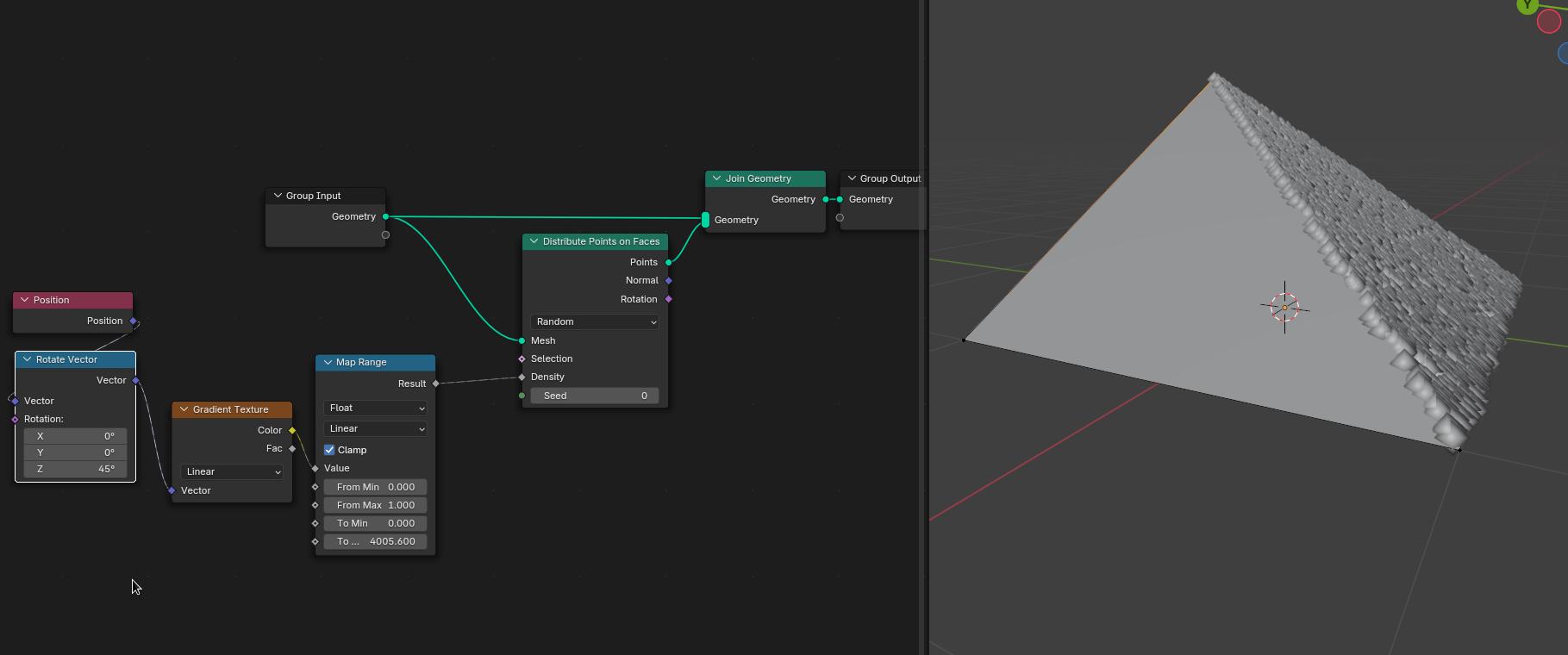
Rotating the gradient aligns it with the triangles. The density value applied to each triangle seems to be the average of the values for each of the 3 face corners.
If you lift one of the vertexes of the plane in edit mode you can easily see the triangles that make up the quad.
Yes, that’s similar to what I’ve experienced in the begininng. One half was filled, the other wasn’t at all. It’s really curious that the plane is made up that way instead of being just one plain face with four vertices.
Sorry to ramble on but I find all this fascinating (and sometimes frustrating ).
Don’t be. I found your additional thoughts on that interesting. Thanks for sharing.
It’s comforting that you say you find it furstrating sometimes. I’m fairly new to blender and therefore don’t really know if things like these are really not that easy and obvious. (I literally just completed the famous donut tutorial the other day and wanted that gradient for my sprinkles on a floor so that I can stage a side-by-side comparison with a previous iteration of the donut.) Coming to this with an engineering background I felt more at home with the thought of writing my own script in order to achieve this, but I was convinced that it should be possible with geometry nodes somehow. They are a form of graphical programming after all.
That is the key to the question, 4 vertices are not necessarily flat on one 3d axis.
All 3d mesh programs are based on triangles, the example of lifting one vert demonstrates why, as soon as the geometry is no longer flat the only way to truly represent a 4 vertex plane using flat faces is with 2 triangle faces.
Nothing is easy until you understand how it works, Blender is an extremely complex program with thousands of commands and options, to learn and understand every single part of Blender is a daunting task that only gets more complex as time goes by!
Nodes in particular are very powerful, that power comes with the downside of more complexity.
I think even the most seasoned users get frustrated sometimes, for me it is part of the fun (like a brain teaser).
Good luck and remember Itaka, the important bit is the experience of the journey!