How to make air vent look like its coming out of a flat surface

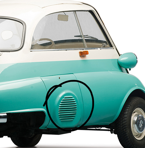
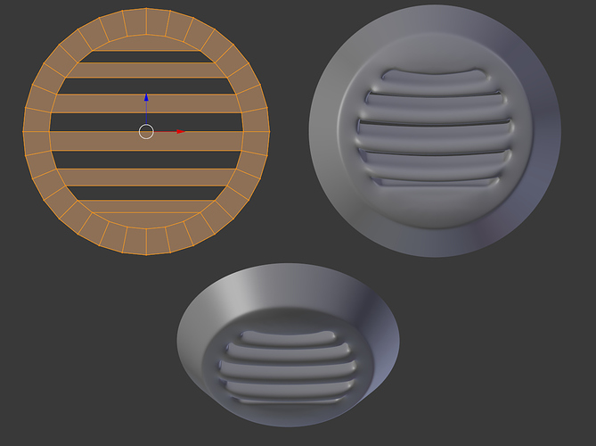
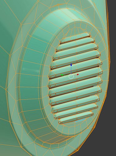
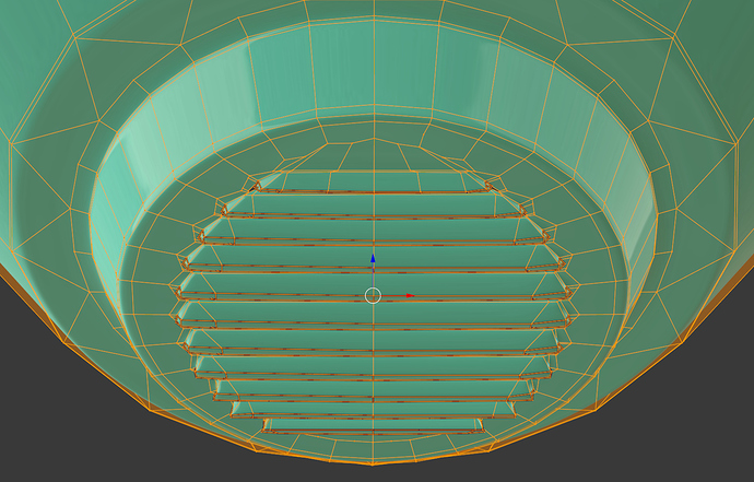
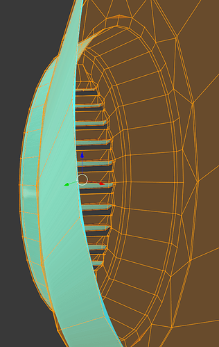
Hey, I’ve been racking my brain trying to figure out how to do these air vent folds that actually look like their coming out of the flat surface (pic 1). Any ideas on how to achieve this given my current geometry? (pic 2)

Many thanks! :slight_smile:

113

bse.blend (441.1 KB)

There are a variety of ways this can be achieved.

Booleans are one, although they can lead to very strange geometry and even artifacts/strange corners/edges when using subsurfaced meshes.

Modeling that area as separate parts and parenting or joining them to the main mesh are another.

Here is a third, which tries to achieve something comparable using clean geometry:

This allows for some clean and easily editable loop-cuts and extrusions:

The end result (number of vents, curvature, sharpness), can be adjusted to your requirements :slight_smile:

For example, if you need more vents, you can subdivide the inner circle and connect faces accordingly, all of which retain their smoothness when subsurfaced and loop-cut:

I hope some of this information is helpful.

Good luck with your project!

1 Like

Hey! Thanks for replying so thoroughly and great advice, not sure why i just didnt think of doing it an easier way. Many thanks again RobertT!

bse1.blend (689.0 KB)

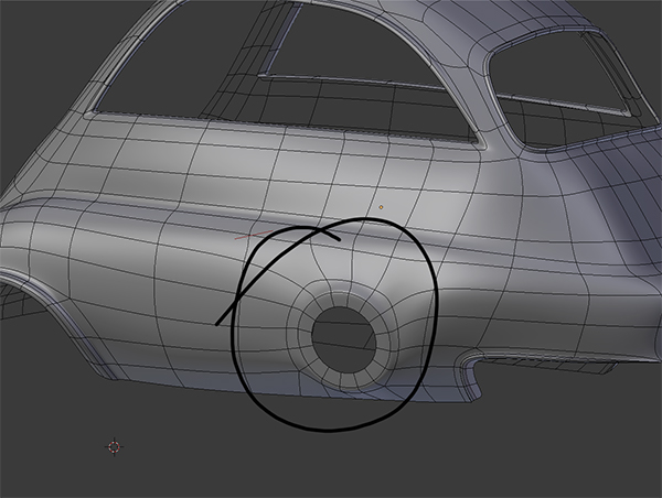
The Isetta engine is on the right, the engine lid (which is the thing you are trying to model) is only on the right only.

Attached you can find the model, but it needs some fixing to match the actual shape.

1 Like

Thanks for providing that example.

1 Like

Wow thank you so much SonicBlue, thats amazing looking! Just out of curiosity how did you do it? Sorry still a bit of a blender noob

I’m no Blender expert either, the thing with hard surface modeling is that you can learn from every software, since the basic principles are the same, in most cases there are no magic secret functions. I believe it could have been done with less edge loops using creasing, but I always forgot about that.

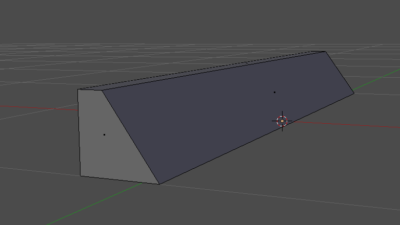
Anyway, the thing is simple, I’ve started with a cube (in reality I’ve extruded the edges of a plane, but it’s the same if you remove the back and bottom faces), shaping it like this:

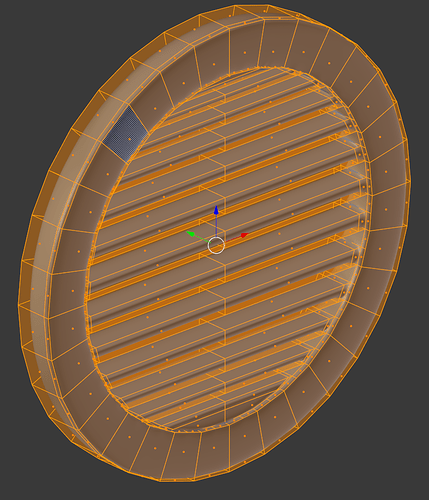
Then, looking at the reference pictures, I’ve added some edge loops to make the correct form (if you isolate one of the fins, it’s easy to see how it was made), at this point I’ve loaded a side picture of engine lid, to match the correct position and size, then duplicate it with an Array Modifier, so that you get 12 copies.

Without applying the Array I’ve compared it to the reference to see if the shape matched correctly, after confirming it, I’ve applied the Array and changed the fin size according to the reference picture, this only for half of it, since the part is symmetrical, you can cut the parts in half and deleted the other one, so that the workload is halved too, then the bridging process started, for some parts you can use the Merge function (ALT+M).

The process continues till you have to connect it to the 16 sides cylinder provided in the file, to do that I’ve placed various edge loops around to help me collapse the edges into quads (or at most a five sided polygon) without compromising the roundness of the original cylinder.

After that, I’ve mirrored the parts and joined the two meshes together.

Done?

No, since the part didn’t match the reference I had to change the shape a little bit on the bottom part, and consequently reroute the edges.

In the end, the more you exercise modeling things, the more you understand how it works, there are a lot of tutorials online, they not necessarily have to be about Blender, you can translate every function, if not, there’s always a workaround.

2 Likes

You’re welcome! :slight_smile:

I had some time yesterday to create for you a somewhat better example using my basic approach above:

You’ll notice there are some additional extrusions and loop-cuts in some areas, and there are some creased edges at the left/right/bottom/outward edges of the vents.

This is an imperfect example, neither identical to your reference photo nor intended to be so.

It’s simply meant to more completely illustrate the direct mesh modeling approach I mentioned in my previous post above.

Best of luck with your project, and take care.

RobertT

2 Likes

Thank you so much RobertT, very informative and so nice of you to take the time to answer my question and do it practically haha many thanks. I shall try it out for myself

1 Like