How to make dashed line/material

Hi!

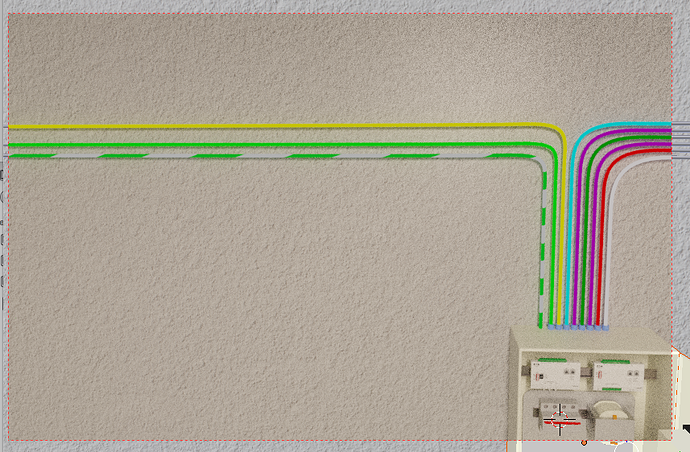
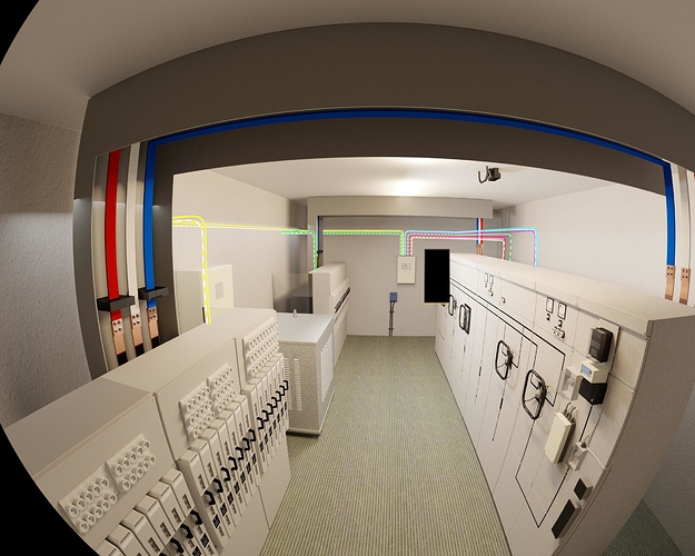
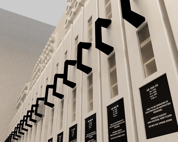
I´m making an of an electrical installation where cables are coloured based on what they´re for, some of them has to be dashed instead of a solid color, any tip on how to achieve that?

At the moment I´ve made a bezier curve with bevel to make the existing cables, and used an emission shader with color to make them easy to see.


1 Like

This thread may help

Hi eivber,

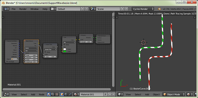
Why not use a wave texture on the bevelled-bezier?


Hope this helps

Martin

1 Like

Looks like it will work :slight_smile: I will give it a go.
Thanks a lot!

I tried your material setup martin, it´s almost there, my curves seems to get stretched dashes when it goes horizontal, any top on how to make the dashes consistent through the whole curve?


try with array and curve follow
to minimize stretch

happy cl


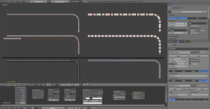
It’s because the resolution is not even through the whole curve but gets divided between the segments (below). Don’t know a way around that, but a mesh can be divided evenly while using the curve to deform it.

Above I made a tube mesh and stretch it along the whole curve by enabling stretch and bounds clamp options on the curve, then use bevel modifier to add segments to it by beveling the middle edge loop around the tube. There are other ways to do it though.

But as such the UV’s are simple and can be used to add stripes or whatnot along it.

Alternatively to save some geometry


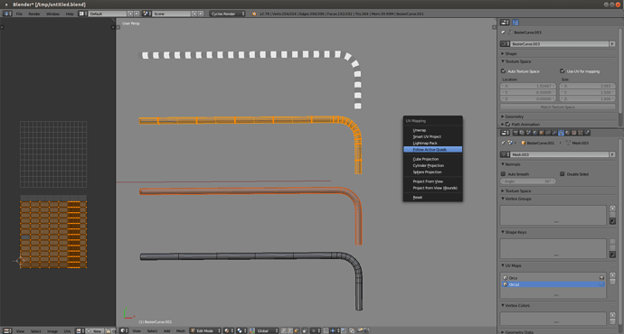
could convert the curve as mesh which also gives the UV’s as real map, and then use follow active quads and length average unwrap method to get the UV’s match the resolution instead of using even spacing.

Use UV for mapping has to be enabled for the curve before converting, and need to select an active face from the mesh for follow active quads. Preferably one that is rectangular so it gives you a rectangular UV map.


1 Like

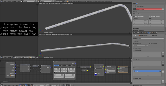
Also try changing what is used as the texture coordinate.
Revided example green bezier curve uses the object coordinate to generate the texture, while red did not have anything connected to the texture coordinate plug:


Hope this helps

Martin

I think Ricky had the best suggestion.

Here’s a file where I used that technique to create an old-fashioned appliance power cord:

cord-test.blend (1.34 MB)

And here’s a Blender Guru tutorial about making a rope where Andrew uses the same technique:

How about Object Coords + Combine XYZ into Checker texture coords? It obviously won’t bend according to your bends, but will look consistent, and might do the trick, depending on what you deem more important - beauty or easy setup. The Combine XYZ is for offsetting the checker if the pipe/cable happen to show a seam of the checker you don’t want to see.

A lot of solutions, I appreciate it!
There´s always a lot of ways to solve problems in Blender, thankfully :slight_smile:

I went with something like Ricky suggested.
Made a cylinder
Did a loop cut
Had a red material on one ring of faces
Had another color on the other ring of faces
Added an array modifier to make a long pipe
Added the curve follow to bend it all

Can then add a couple of loop cut´s to the cylinder if I want smoother bends, and increase resolution of the curve.


Glad I could help
can you elaborate on the scene ?

sort of an elec room HV ?

happy bl

Of cours, if you´re interested that is :slight_smile:

Short about me:
I´m an electrician and have been for 10 years, in addition to that job I started my own one-man-company where I in the evening makes electrical drawings, fire and escape -plans etc. in AutoCAD for different customers.
I´ve done some 3D in the past(3ds Max at the time) but never really got serious, the only work that was ever used was a cd-cover I made and an overview of my apartment wich was a part of the ads when I sold it.

I had tried Blender before, but I guess it was pre-2.49, cause then all the buttons was at the bottom. Could´t figure out anything, ended up uninstalling it.
A couple of my older colleagues is taking a higher education within electrical works of some sorts and asked if I could do some 2D drawings for some essay or something they were working on, wich were gonna show the class how to solve a certain challenge, exchanging two old wheel-switches for some modern electrical remote-controlled switches with arc-flash-protection system to protect equipement and any persons close by from damages from the explosions in case of a short-circuit.

I had just started fiddling with Blender again at the time and suggested we could test out the 3D world instead, so I went to start on this heavy uphill battle of a learning curve to learn modelling, texturing, node-editor, Cycles, animations… it´s a huge thing I suggested for them, but it´s starting to look like something, apart from just learning Blender itself, you spend a lot of time solving small things like this, I made coloured lines to show where cables go, and they asked if I could make a dashed line… simple things often take a long time to figure out, but thanks to you guys, not much research was done.
A lot in this scene could be better, but even at this level, the guys are gonna deliver a presentation wich is way above all the other students´ presentations when it comes to visualising how they plan to solve the challenge, so they´re super happy with the results.

I´m not satisfied with the shaders and such at the moment, but I probably have to leave it because of time limits, and also, people who´s not used to CG think it´s awesome and photo realistic, but for us who´s used to CG, it´s got along road ahead before it can be mistaken for a real photo :slight_smile:
I still have the animation part left wich has a heavy learning curve as well, so there´s probably gonna pop up some posts in here about that too :slight_smile:

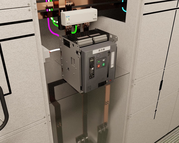
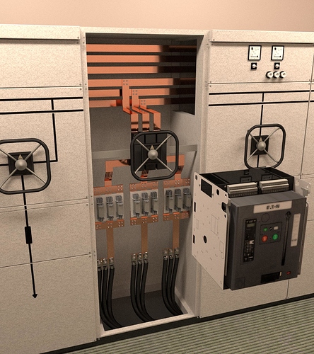
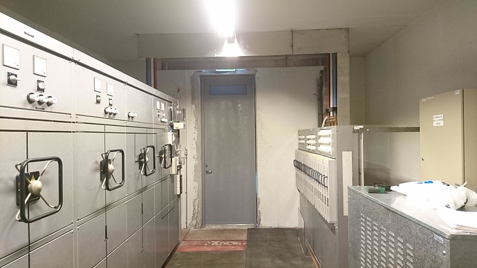
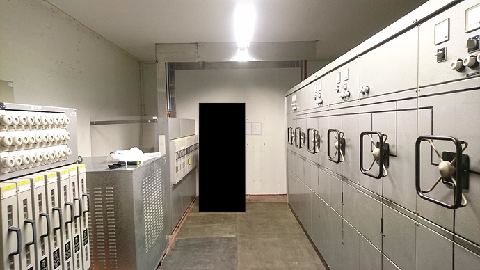
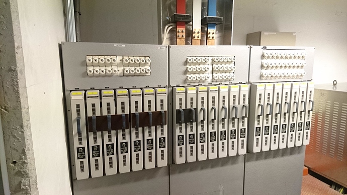
Will post a couple of pictures from the real deal and some test-renders and an early test-animation.
The test-render was rendered at SheepIt, but some of the decals on the cabinets disappears in some frames, dunno why really.
Also render times is one of my problems, if the projects end up with 1000 frames or more it´s gonna take a while to render out.
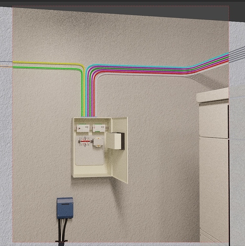


Some pictures of the real-life room.


thanks for the details
can you give a brief description of the different parts from an electrical point of view

find it very interesting

You need a lot of practice to get a more realist render
but it is a good beginning and certain it will improve with time

the more you use it the better you become as a modeller LOL

thanks
happy bl

Do not eat upside down? :smiley:

Well, this is not the type of installation I typically see in my day-to-day work, but when a short circuit happen I guess it will last as long as 300milliseconds before enough stuff is destroyed so that the “explosion” will stop, this allows so much power to be released that the cabinets aren´t strong enough to protect the electrician outside.
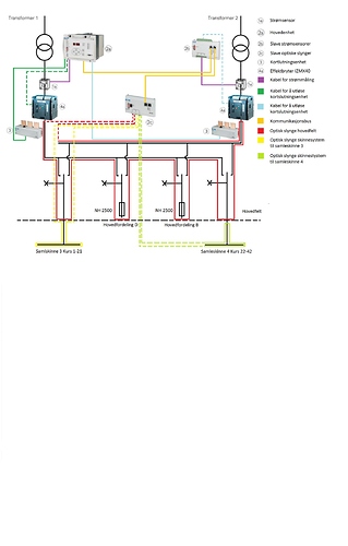
So these guys are suggesting that they exchange the old switches for some newer ones where they can attach this protection system that cuts the “explosion-time” down to 1,4millisecond, and then protecting the electrician and nearby equipment.

There are installed a lot of fiber cables around all those square cobber-lines(don´t know the proper english name;)) with a lot of peeking-holes wich senses light/flashes that occurs during a short circuit and then cuts the power.

Heres a video showing the system

interesting

is it using the one with explosives to cut the circuit ?

but if I remember well it is expensive but does give maximum protection

in which country is it ?

happy bl

Not really sure, I just get some instructions on how they want it animated and do as told :slight_smile: It is of cours a good thing that I work in the field myself so that I more easily can grasp the concept and what things must look like.

We´re from Norway, but don´t think this system is much used here (according to Eaton themselves).
My friends/colleagues have talked a little with Eaton themselves in Austria to make sure they set it up all correctly, especially since they´re installing it into an existing system.

Heres a drawing showing the system:


do you happen to have the English name for this system

I cannot read it do you have the English version !

I do remember checking out some Super high speed method to reduce the equivalent RMS short
but it did use explosive in the Fuses
but this will open inside a few dozen microseconds
only delay was in detecting and activating the charges

I mean way faster then normal fuses

but also takes a lot of space
and need minimum safety space for security

And also need to look at amount of overvoltage generated !
might be a problem too !

thanks
happy bl