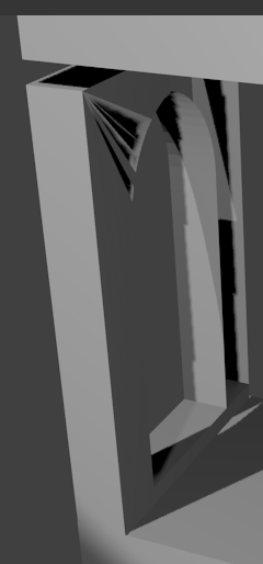
I’m looking for a method that allows me to create an arch like that:
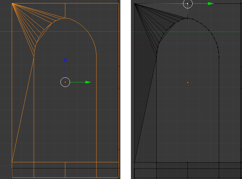
I tried to start from a circle, then to remove three quarters of the vertices, and then to extrude some of them, getting something like the second pict shows, but i encounter a problem filling the face (as the first pict shows). Well, do you know a simple method to model such an arch?
That’s a very high detail arch. Check out 3dMedieval’s tutorial here: http://3dmedieval.blogspot.com/2010/12/modeling-low-poly-medival-arch.html?utm_source=BP_recent.
Well, I don’t want to model this triumphal arch, I only want to know how to model the base shape which made it up…  only wanna know how to model a semicircular arch like that
try hitting ctrl-N. what i have noticed happen sometimes when extruding circles and other outlines is that the surface normals get messed up, they face in opposite directions. ctrl-N aligns them so they do not all of a sudden flip (one face’s normal is pointing up, and an adjacent face’s normal is pointing down. you want them to both face up).
and it looks like you have an extra edge in there…
Using 2.57, i would do the base shape like this :
-Add a circle
-Cut the lower half of it to have only these vertices remaining :

-Select the 2 vertices in the extremities of this half circle, press E to Extrude and bring them down.
-Extrude again etc… until you get this rough silhouette :

-Select All and press ALT+F to fill (or Mesh -> Face -> Fill )

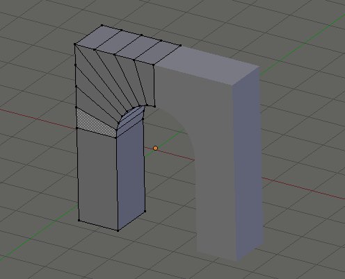
-Select All and press E to extrude and get the base shape complete :

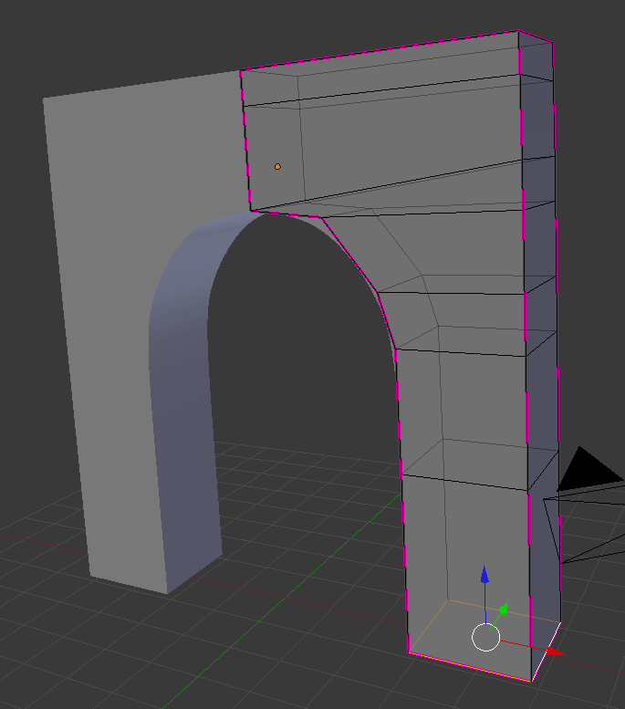
I had a play with the notion. See the attached image (click to view full size). I started with a cube and simply extruded it up wards a few times. I then increased the width of one size of the cube segments … wider at the top and getting narrower. I then added a mirror modifier to make the second half. Finally, I added a sub-surf modifier to smooth out the curve. For the exterior (non curve) edges, I applied a 1.00 value crease to keep them straight. This results in (I think) an ultra clean model, easily editable and with a very low number of faces.
Neil
Another way to do it is this.
Add 2 circles with the same number of verts and delete 3/4 of them.
Then select all verts and use the LoopTools/Bridge tool to fill the faces.

Straighten out the outer circle, use LoopTools/Space to space the verts evenly.
Extrude down to form the leg part and extrude to get the depth.

Add a mirror modifier.
Simon,
I like your technique. For the first part, to create the two circle quarters, I’d personally create a circle (Mesh primitive) and then extrude it. That feels like a cleaner workflow and means that there is no creating two circles, messing with each one and then bridging them.
Neil
agreed, simon’s method with kolban’s variation - all quads, neat method
Thank you guys, that looks very very good. I’ll try and I’ll keep you updated:)
I’m really sorry that I reply SO late… ![]()
I’m having problems doing this step… can someone help me? ![]()
I select all the vertices of the mesh (as displayed in the second pict), and then I select LoopTools/Space, but nothing happens. Same result when I select only the outer circle…
Try to use the “Space” loop tool after you straightened the outer circle, circles have usually already good spacing between vertices.
By example after straightening (selecting somevertices and pressing S then 0 then X or Y or Z depending on the direction i want the vertices straightened) the extruded circle, i have this :

I select the side in which i want the vertice evenly spaced

then click on the Space loop tool

It should then work :

Oh yeah!! It worked!
My problem was the straightening! In fact I would never hit 0 as you said… but it works! What exactly does the hitting of the 0 while scaling some vertices?
S-key then X or whatever scales the selected vertices to the current pivot point. As long as your pivot point is set to Median Point, this will make all the vertices have the same X coord as the median (i.e., “0” is the secret code for “have the same coord”. “-1” is the secret code “mirror your current coord around the pivot point”. Otherwise you put in the desired scaling value ).
Keep in mind that the pivot point is controlled by the pivot point tool in the lower menu bar. If it happens to be set to 3D cursor instead of Median Point, all the selected points will suddenly have the same X coord as wherever the cursor happens to be.