How to model this table leg?

Hi there!

I have to model this table leg:

I tried to use a cylinder as a boolean:

However, when the curve starts to rise, the small cilinders get more slanted, until they are at a 45 degree angle:

Is there a better method to model, in order to maintain all the small cilinders top plane perpendicular to the floor?

You might not believe it, but I modeled it over a year ago, but I just can’t model it the exact same way…

P.S.: Even more than the top faces becoming perpendicular with the floor, I’d like them to “flow”, i.e., not having steps.

The other way around is easier, align them along a curve and then boolean or even just scale the lower part flat.

If you don’t mind the hassle, you can do a Z-axis return to 0 on each circle with a tilt

That could be a solution, albeit a slow one.

I’m sorry, I’m not quite following you…

yep, it’s a dumber way to do it.

I meant it like this, here’s a geometry nodes setup instead but I hope you get the point.

You align the cylinders along a bent curve. Then you mark the lower points of all cylinders and scale them flat to even height.

Thanks! I have yet to learn about geometry nodes, but I’ll surely try to replicate your setup.
What if I want the top faces to follow a smooth path, and not be perpendicular with the floor?

Not sure if I get the question. Isnt that how it was with your boolean method?

1 Like

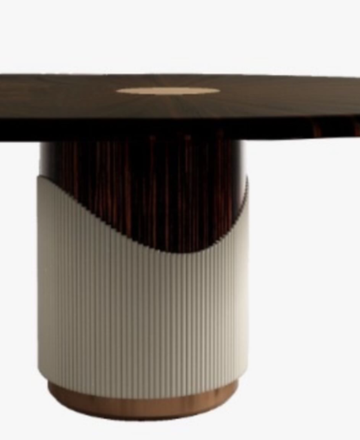
Yes, but as the cylinders started to get taller, they would start to lean to the inside. It’s hard to explain but I want the top faces to flow, but at the same time not slanting to the outside or the inside:

Can’t you just apply the geometry nodes instances, select the top faces in x-ray and then with individual origins scale Z to 0?

I’m not sure what you mean by “flow” as in the original photo, to me, it seems like they step from one cylinder to another.

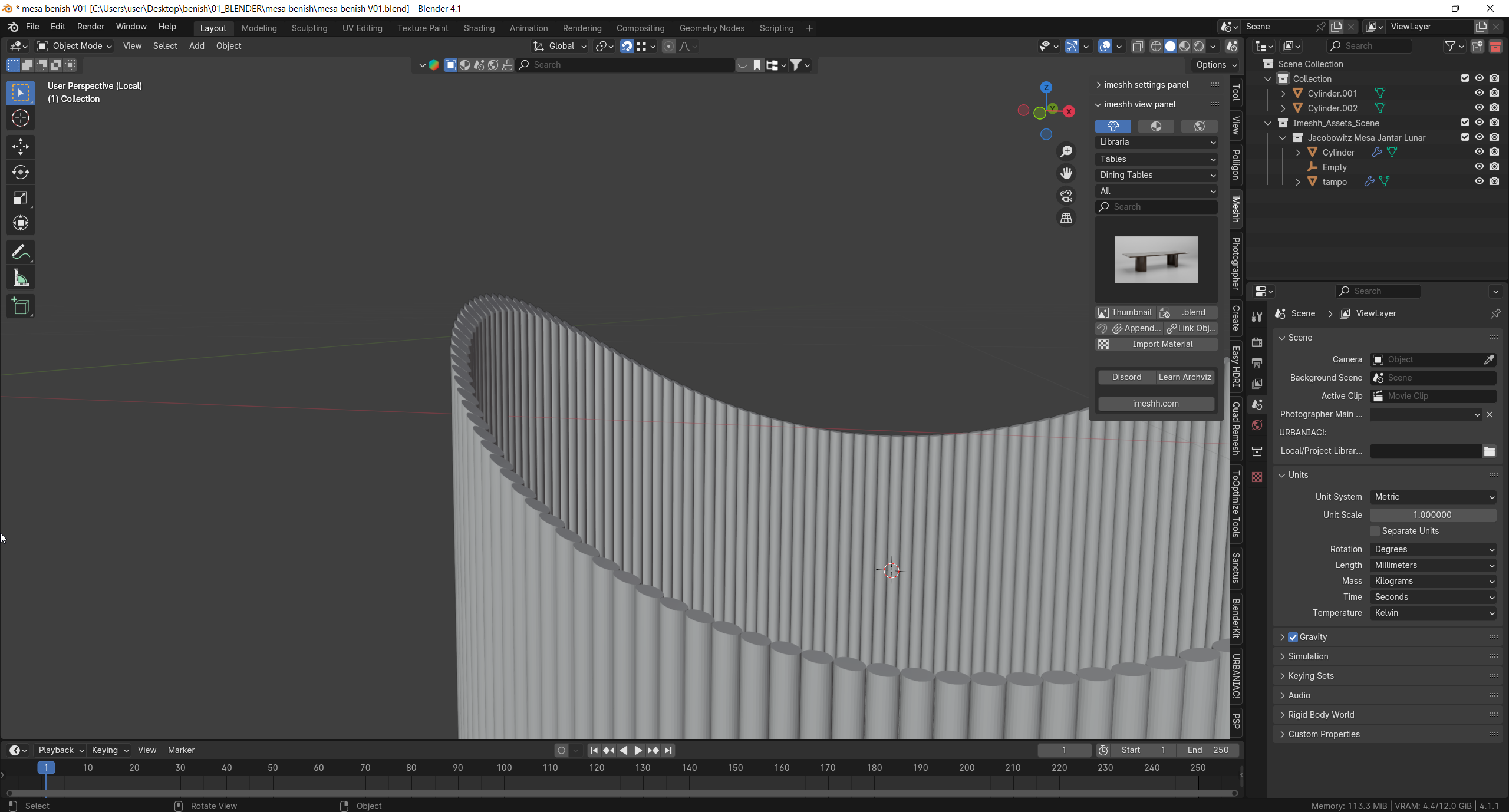
Oh you want the slope to be aligned to the curve direction and your cylinder slope isnt like that.

Yeah ok. Well there are several possibilities. You could go on with the geometry nodes setup and align the cylinders topfaces to the curve height.

But if you dont know geometry nodes well its perhaps easier to use the bent curve and convert it to a mesh with a square profile. You could use that result to boolean as you did.

If I apply the geometry nodes instances, and select the top faces with individual origins, wouldn’t that create a staircase effect?

You’re right, in the original photo each cylinder step to another; however, I’d like to try a smoother approach.

You referred a bent curve, and to convert it to a mesh. I understand what you mean, but I don’t have a bent curve, and I can’t see how can I create one after having applied the boolean modifier to the cylinders…

I meant you could use a geometry nodes output/result to boolean with.
Use this one:

In the quadriliteral node you can set the profiles size and in the multiply the amount of sine waves along your ring.

2 Likes

Thank you again, you’ve been quite helpful! Are there some geometry nodes tutorials that you recommend?

Well there may be others here who know that better. Just search on youtube for geometry nodes and beginner. I am pretty sure there are quite some good introductory tutorials there to get a good start. Just choose one thats not older than a year or so. There was a geometry nodes version in blender before that was very different.

Thanks, will do just that.

Oh, if it’s not too much hassle, could you provide the file that you created? It would be awesome for me to learn from.

1 Like

Cylinders.blend (977.7 KB)

2 Likes

You’re the best!

1 Like