I want to rig this kind of hing and do not know how to do it properly in Blender. It could be very nice if some of you can give me some ideas about rigging this as on the video, but I will be satisfied with simplier solution when the window is going to be opened to the position 90 degrees. https://www.youtube.com/watch?v=Ec2-QXsxAmY
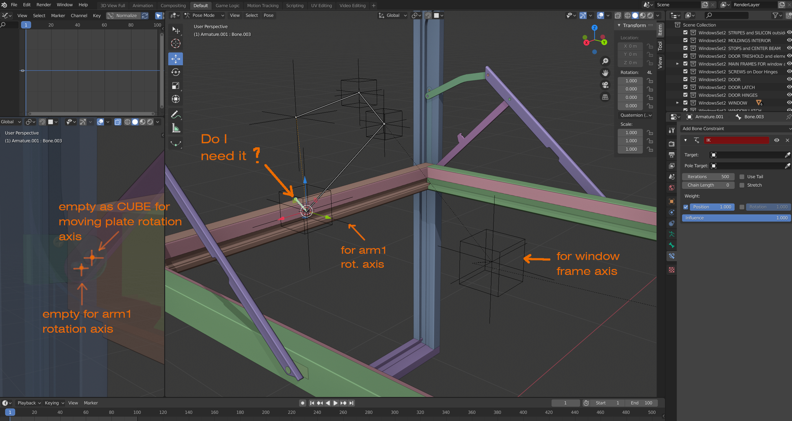
You can see I started to use bones with two IK chains, but one axis is not on the place and one arm is changing angle. How can I solve it?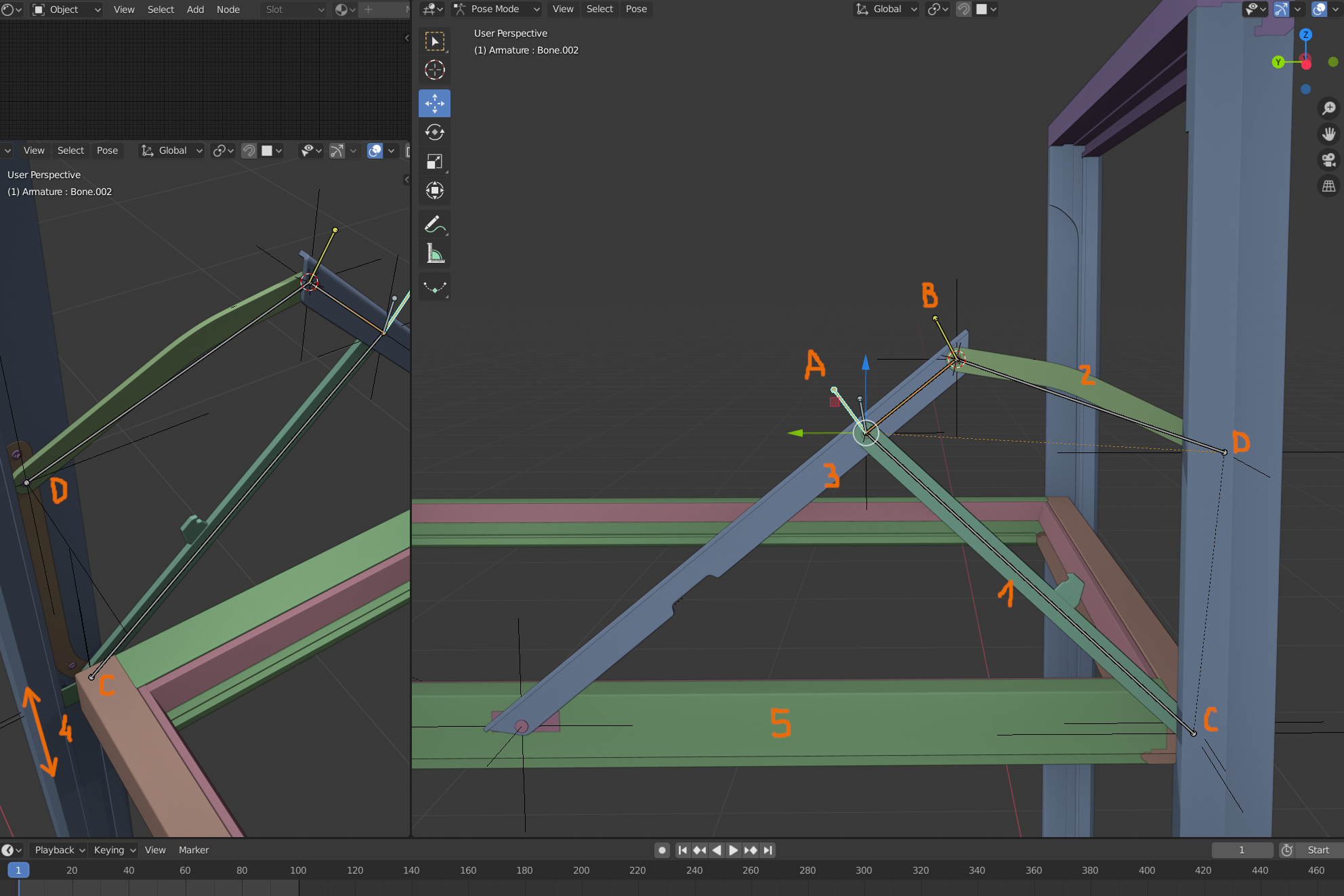
To be honest, with that, my gut instinct is to have separate items with appropriately positioned origins and do it via parenting and constraints as you want each thing to react to the movement of another, not sure bones would behave in the way you expect. Though rigging isn’t my forte so maybe someone else can suggest a suitable armature setup.
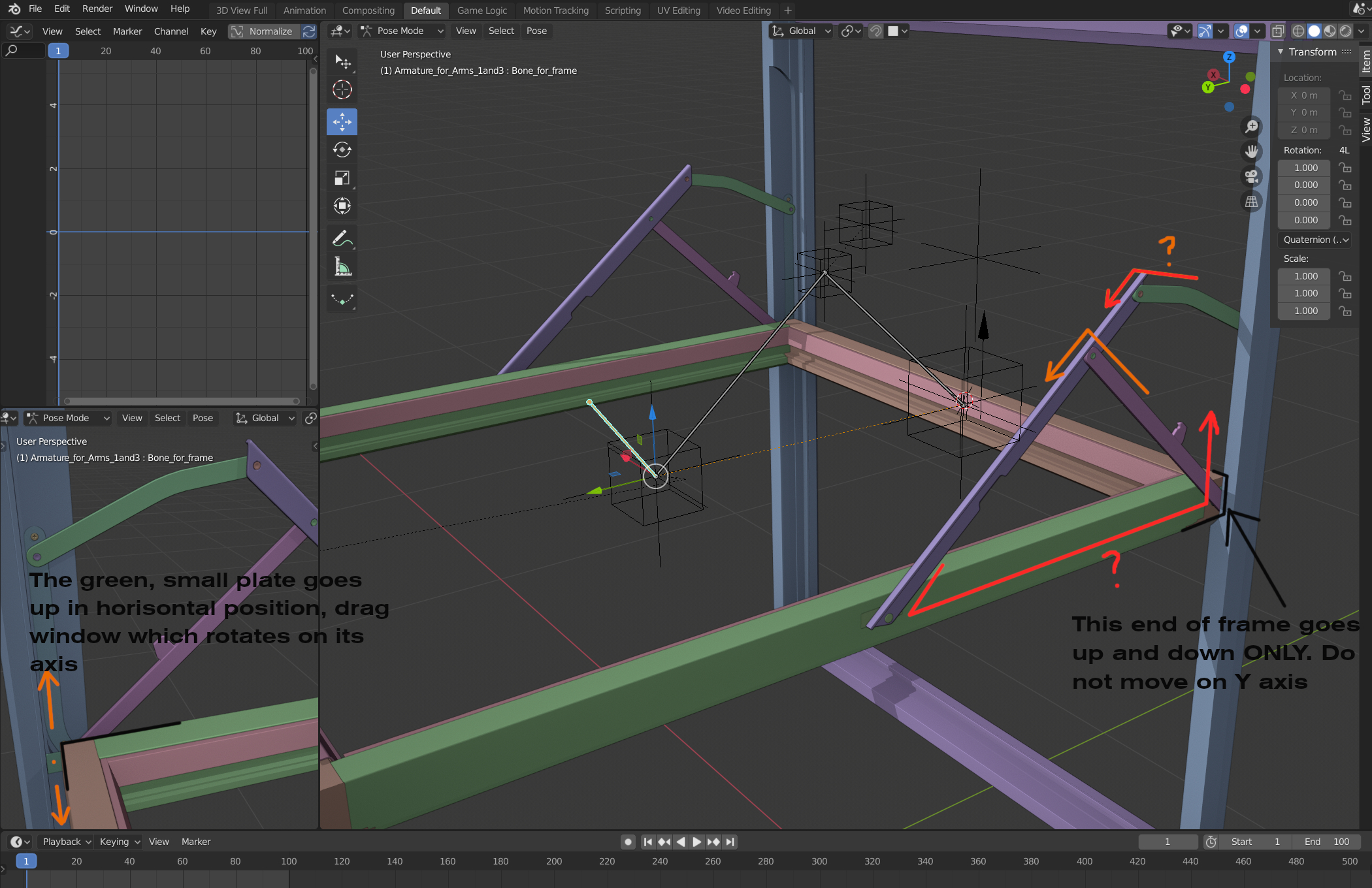
I tried constraint Look At and others, but it did not work for me in this case. But! I have almost no experience with rigging complicated things. Everybody show basic tutorials and I am still trying to experiment myself. I did new rig with bones, but still I have no control. I am trying to make separate armatures and connect them, but how. Linking is changing the behavior of whole thing. What should go first? First I thought it is the small plate which pulls window frame up or down, but we can see this also as the arm1 is rotating and then 3 and 3 pulls the frame(5) at the same time with small plate(4). So theframe(5) needs to look at small plate(4).
Indeed, I have similiar problems myself regularly, you have an idea, but all that is ever shown is a very basic example and you spend forever chasing your tail in order to find a solution.
Here’s what I would do:
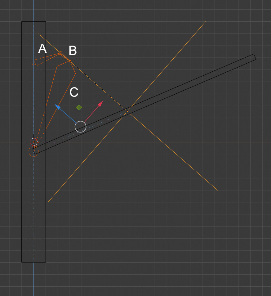
The ABC armature chain has an IK solver, targeting the window
The empty pivot is parented to bone B
The window has a track to constraint targeting the empty pivot.
This way, moving the window up and down changes the angle of all 3 linkages, while keeping the sliding pivot point constrained to the edge of the window frame.
All my dimensions are just eyeballed, so it doesn’t mechanically line up, but yours looks pretty carefully modeled, so things should work much better on your end
Great that you are helping. It looks promising. I have tried to do something but still I am not sure what is what… What I have now is
looks good to me, is it moving appropriately?
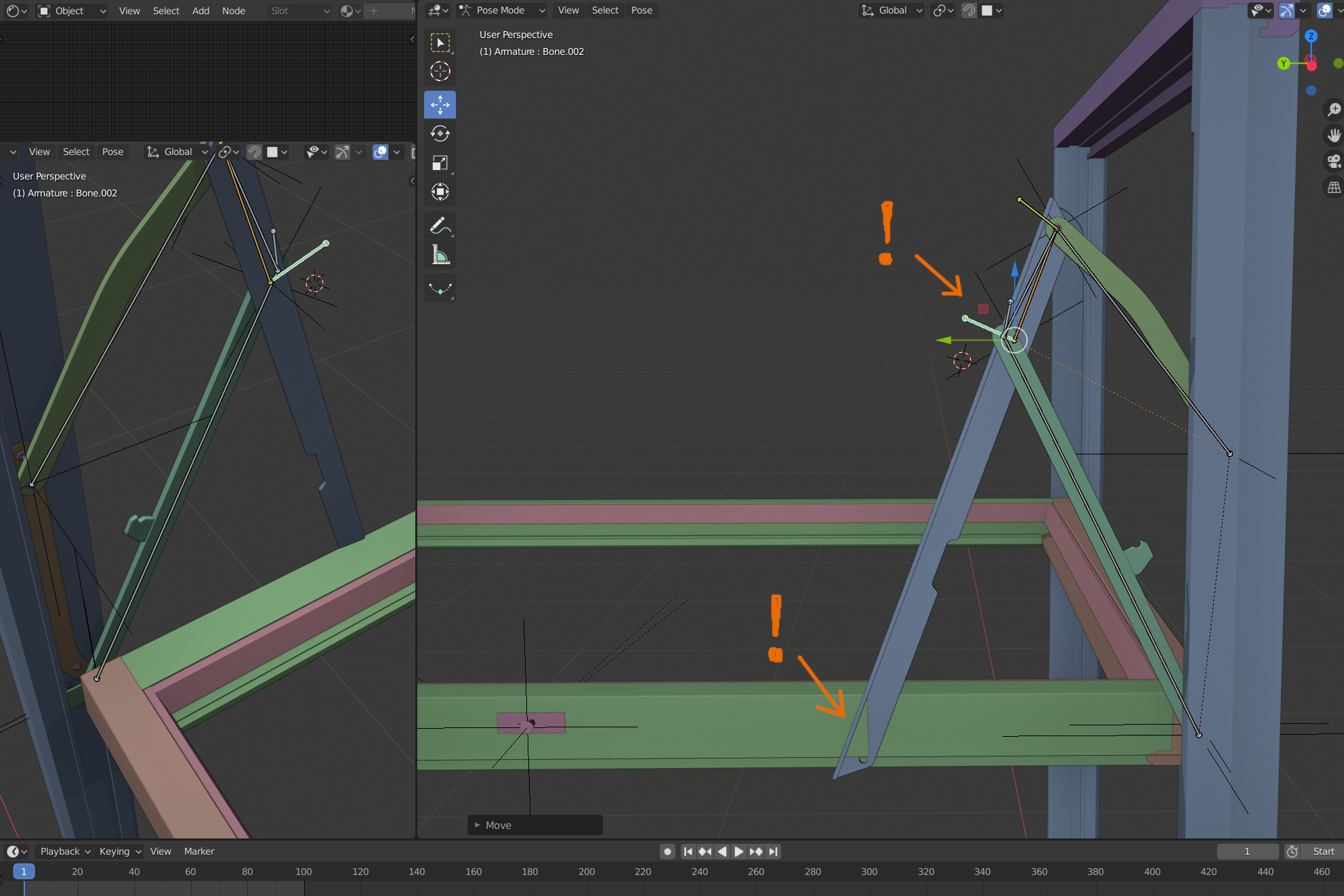
Arm1 is not connected to its axis after moving IK chain. Arm1 is BoneC in your illustration. Can you write what do you mean “targeting window”? I am not sure
The IK constraint has a target that it will move the end of the bone chain to:

You could set the empty that controls the movement of the bottom plate as your target, it may need to be adjusted for side to side alignment.
I almost have it, but still it is not precise position for frame and sliding plates during the movement. The frame is being placed, let`s say correctly, but the sliding plates hava been moved from its proper position on the frame
On the right: view of the plate in its start position.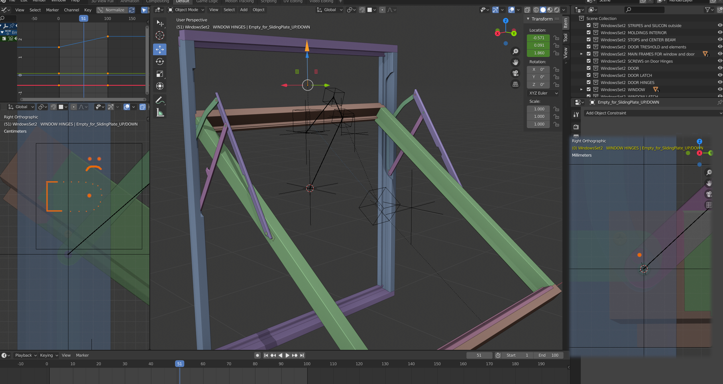
Hey, When rigging this type of things, it is based on Euler’s quadrilateral theorem or something of the like (I’m no mathematician by any means) but basically the linkage lengths and pivots of two sides have to equal the other two and that has to be equal to 360 degrees. I wish some one would have told me this many years ago too 
So proper placement and length really matter, at least to get it working correctly. I found an old file I did back in 2.6 version days, it seemed like the same type of thing(window) so I will leave you a link to the file so you can get another idea - keep in mind it does use an IK and a driver, the gotcha in this or anything you rig with an IK is when it is collapsed onto itself (window closed) it does a little flutter at first. There are several ways to rig this, I myself have a habit of using drivers for stuff like this, anywho here is the link
DISCLAIMER; This file is saved in 2.76 - if using 2.7x it will open fine, if using 2.8x APPEND the ‘objects’ from the Object folder.
Thank you for the answer and the blend file. It is working well, but I rotated it in view because my window is opening this way. It means the hinge is not in the same position. I am trying to analize your rig and undrestand all rules in 3D rigging (in Blender or Max very different than Solid Edge or Inventor) I will be satisfied if this will be like this now: opening to 90 degrees, but maybe there is solution to do it as you can see on my mobile video? rotating to 180 degrees. Can you write the step by step how to build this rig and why this and this…? So we have this now (your rig opended in 2.81):

Hey, I posted this file as an example - I just found it in my archives - I don;t really ever remember doing it, but it was in all my stuff. Do you have windows that open differently - some from top some from bottom ? If I remember there is a limit constraint on the bone that gets rotated - but not sure what will happen if its disabled or removed due to that bone that has the driver(it keeps the window in the frame, sort of). There is probably a better way to due this, with out using that tracker bone. having an example would be much better for helping purposes - I have never rigged or used any of the programs you mentioned - but the last 2 are CAD programs ,so I’m sure they are more capable. As far as writing this all out - IDK, thats really not my thing, not to mention the time involved - you see where I’m going with this… 


But I am happy to help you out
Yes, I understand and I am happy that you all guys are helping me. All these ideas and solutions pushes me to find a solution and understand it. I want to study everything about rigging and constraints. I believe that Blender is most powerfull software in maaaany areas and there is some good, proper solution as in cad softwares. If not, I will contact “Blender experts” that maybe there is a time to make some improvements in this area. Of course engineers stick to Solid Edge and Inventor, but if you get a file from them for making fancy visualization with animation of mechanical objects, it could be great to have right solutions.
Hey, While I was working on some other file I had an idea for this, it is still just a demo file because I don’t have your file - but this one works like the real window does (I hope). BTW - we call this type of window a ‘casement’ style, usually has a crank handle to operate _ at least the one in my bath room does. Any how this still uses a driver because I realized that the rotation of the window is actually elliptical - so hence the driver for the rotational part. I did not leave any extra crap in this file , like the last one, sorry about that, usually do a better job of checking for that stuff.
Forgot to mention I left this rig ‘posed’, I think it works better (more like the real thing) from a starting point - not to mention I built it opposite/ upside down
DISCLAIMER; This file is saved in 2.76 - if using 2.7x it will open fine, if using 2.8x APPEND the ‘objects’ from the Object folder.
1 Like
Hi! and thank you very very much for the file. It looks exactly how it is in reality and how you see on my mobile-video in the link ( https://www.dropbox.com/s/bdj4bj9rcqxoy7e/window.mp4?dl=0 )
I was working with another projects and had no time to check it, but now I am back and I will try to do it on my model. I will write about results.
1 Like
I think you are going about this the wrong way -
I would have 1 animation per part that rotates -
the parts are parented to each other - no IK
use a driver 0-1 to rotate or slide each part
it will give the illusion of a armature
- with IK we can’t have dependency loops - but in reality we have them all the time -
in blender game engine (UPBGE) and in the viewport we do have rigid body joints, and forces
this could likely simulate something like this better than IK
I thought the OP had posted. The rigging was not really the big issue, it was getting it to replicate the action of the real thing - which is elliptical in rotation, that was not solvable with out a modified driver curve - I think I may still have the file if you want to see.
Hey BTW, I was just looking thru your sketch book last month for some help on something and was wondering where you had gone, I miss some of those things you used to post. 