Ocean Water is also easy, just apply a material I made a little while back that involves some bump maps, animated gumph and so on. You can see it at this link
But how can I texture the land to a reasonable degree?
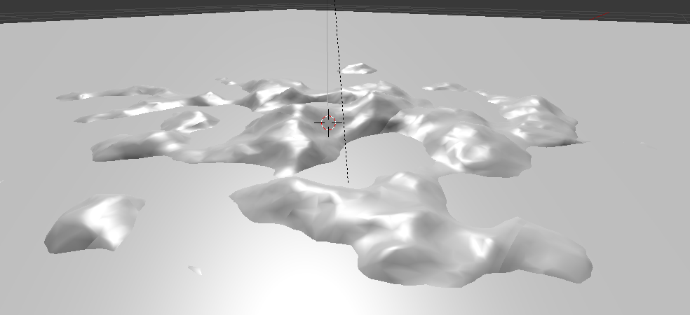
It doesn’t have to be perfectly realistic as it’s just for a racing game on the water. Because of the structure of the land, it also can’t be pre-baked or require any object/mesh specific data (ie not vertex colours). Vertex colors are the method I’ve generally used in the past, but as each chunk of land uses the same mesh, just displaced differently, I’m unsure how to proceed.
Here’s a blend to play with: island.blend (916 KB)
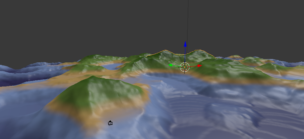
Simply by using a horizontal color band in the node editor I can create:
Hmm, some really good stuff there. Unfortunately all the pieces of terrain share the same mesh, meaning: They share the same UV map.
Hence, using stencil textures won’t work, as the different parts of terrain will require different stencils.
Maybe I’ll have to give up on keeping them the same mesh.
Well, I’ve decided on a plan of attack:
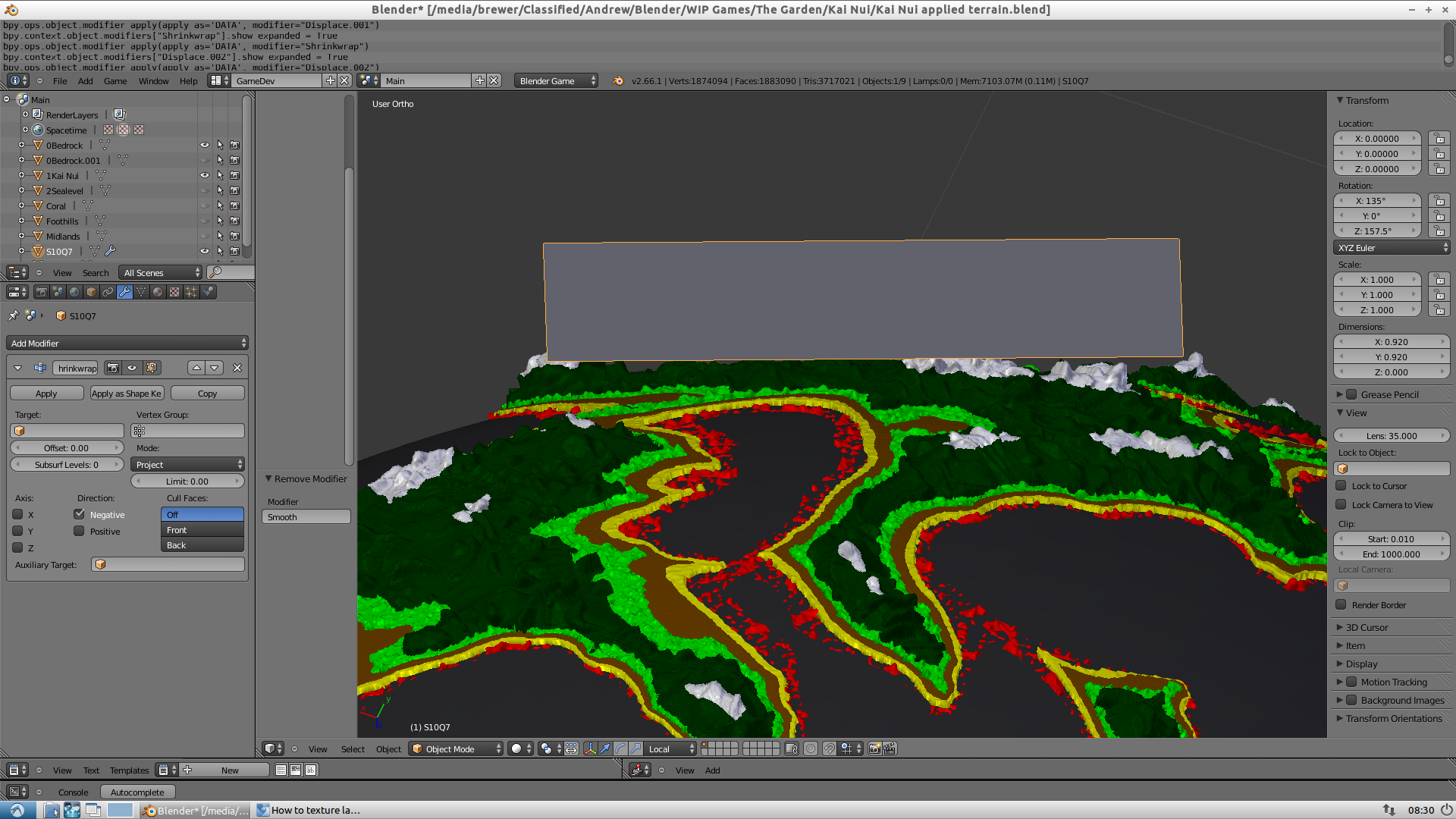
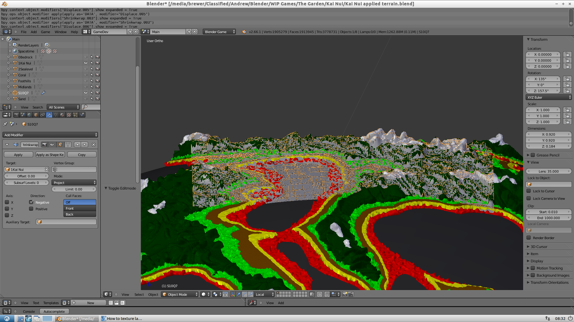
An external heightmap is mapped to a selection of mesh, where a displace modifier converts it to geometry.
The first frame of runtime, a script:
Sets the red channel of the vertex colors to the altitude (with a bit of randomness to break up the visual lines)
Sets the blue channel of the vertex colors to the slope of the face (again with a bit of randomness)
Sets the green channel of the vertex colors to random values (Which tweak the coloring of everything slightly. I may think of a better value to put here)
A node-based texture then extracts these channels and uses them to layer textures on top of each other.
Advantages:
Small file-size. A heightmap is ~100kb, a plane subdivided/displaced using modifiers is tiny. No large maps of where textures go either
Can change level simply by feeding a different heightmap into the file before starting the blend-game. (ie by a launcher application)
Easy to make levels
Disadvantages:
Low customizability. Whatever heightmap you use, the results will be visually similar.
— News half an hour after typing the above: —
Darn. Vertex colours and modifiers don’t mix. It seems that if you have a displace modifier on a mesh, you can’t alter the vertex colors. I may file a bug report on this because it seems silly.
– Another Half hour: —
Manual displacement by a script in the first frame works quite well really.
Done:
Extract height data and displace vertices
Color Vertices on altitude
Started:
Recalculate Normals. Some seams still visible unfortunately.
Layer Textures together based on vertex color. Currently a simplistic model using plain colors. I need to integrate image textures into the node setup.
Not Done:- Recalculate Physics (shouldn’t be hard)
Different LOD should be easy to make, just use a different res source mesh.
Unfortunately this seems to run really slowly. I’m only getting ~70FPS on the 30,000 mesh. The one in the first post was also 30,000 and got ~ 180FPS. Is this how much voom it takes to drive the node material? Because the displacement is done only in the first frame.
Use the x and y normal values to determine what’s a slope. Why use a modifier? You can generate your own HM:
Manually generate the desired map (ANT Landscape, image based, hand made, you name it)
Collect the vertices positions and elevation in a dict, with their x,y positions as keys.
Loop through the dict in a grid like order, with a for loop, and place the z values in a list.
Save the list into an external file.
The list can be used in various ways, you can just use half the list or every second value, for various levels of detail.
You can also use a mathutils noise function like mulitfractal or turbulence or in combination with the HM.
Simplify your nodes material : use as less multiplications as possible, small textures.
Use big meshes vs many small ones!
@Torakunsama
I’m not using a modifier any more. For some reason it kills vertex colors. Using it would have simply made my life easier!
And to deal with heightmaps, I’m using an image. I take the UV position of each vertex, multiply it by the image size to get a pixel number.
I then use the videotexture library to open the image into a python list. I then sort the python list slightly to make it into 2 dimemnsional array, and then do a lookup using the vertex position. I take the color of the pixel underneath it, divide it by 255, and set it to the vertex z position.
@CaptainAndrew:
Thanks for that first one. It provided some information I needed.
What do you mean by ‘the convex nature of my planes’? Do you mean that you want cave-like structures?
No it was not the method mentioned there, but it was similar.
As I applied the heightmap, I also mapped the height to the red vertex color (in python). I then fed that through the gradient.
Catch a blend if anyone wants to look: Progress.zip (633 KB)
I meant to say that my initial plane mesh is not flat. I wanted to model my terrain and shrink wrap a heavily subdivided plane to it, then bake that plane to a height map, but because my terrain is part of a planet, the plane ends up with the planetary curvature (convex) after the shrink wrap, which doesn’t work so well with baking to height maps. In any case I have decided to dump the height map procedure for my project, but will definitely use it in future non-planetary projects.