Hello, this is my first post here and I am new to blender.
I’m coming from AutoCAD modelling, a while back…
Below is a sketch of mine of what I want to model :
Specifically the cornices. I’ve started the model and have the walls layed out.
From my brief aquaintance with Blender I have a couple of ideas.
I want your input to understand if I’m thinking the “blender way” about this, since I’m coming from a different modelling background.
Start with the lower cornice - the L profile protrusion:
Extrude edge on four sides of the room, from the wall horizontally making an horiz. face.
Then extrude the edge of that vertically
Then tilt that in.
What about the small top cornice, with the more complicated profile?
Make a path as a wedge against the top corner, in section.
Then boolean add to have the corners.
Who finds this odd and has a more obvious way?
Thank you.
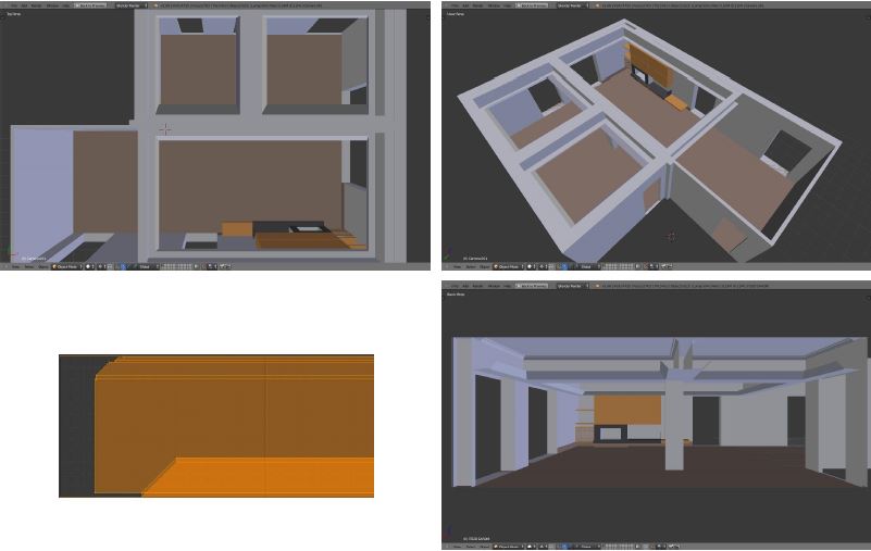
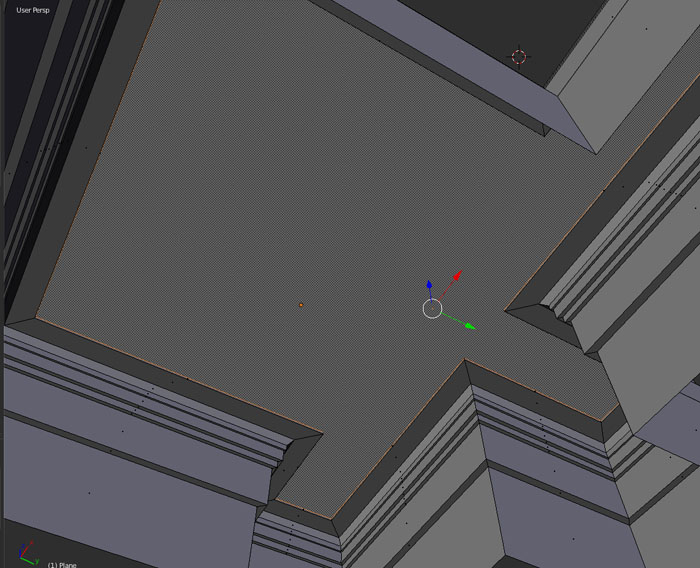
Here is a screenshot of my first Blender model. I started with the walls.
The wood screen goes to the area highlighted in yellow.
The cornices crown the walls
to create tubes and other (industrial extruded shapes like wiring, or chair legs) simple use nurbs, you can loft a nurbs circle over a nurbs path, (you can even adjust size of the loft by another curve and so vary size… but lets forget about that for this).
After you’ve done that you can change the circle to match your profile.
The nice thing about these nurbs is that while the circle was lofted over the nurbspath, you can still deform the nurbs path
So you can bend the path that the lofted object folows, so you can make rounded shaped curves.
If you want straight corners between walls, then you can simply copy a non bended nurbspath, and turn that path as object 90 degrees (R + Z + 90).
Perhaps make a profile with a bézier curve, duplicate (shift+D) corner edges and separate to their own object §, convert to curve (alt+C), set the spline type to bézier (tool shelf, edit mode), and set the profile as bevel object in the curve properties. Then scale down profile curve as needed.
I would try to keep things simple. Booleans, beziers, paths, nurbs and bevels aren’t simple.
Make the walls with square corners, then add the cornice. Make the profile of the cornice with verts and edges, move it into position in the corner, and extrude it along the wall. When you get to the corner, scale the end up in the x direction (assuming you’re extruding along y and want to turn the extrusion in the x direction) by 1.41 (square root of 2). Hot key: S, x, 1.41. then rotate the edges 45 degrees to get your miter joint, and proceed to extrude in the new direction.
Bezier paths are verry simple if this short video 3 minute isnt simple enough
Then just add (menu curve) curve path
in object mode also (menu curve) add a nurbs circle
Click the curvepath in your view screen, on the right side screen; the side menu with the small icons (camera / world/ material …etc) there you find an icon that connect 2 dots with a line … there you’l find “Bevel object” under it a small still empty field starting with a box icon, just click it, and then select your nurbs circle.
It isnt any harder then that…
You can do more with a path if you go in edit mode Press E, to add more points easy.
Or be wild and tryout another nurbs path to use as an “object tapper”
This isnt hard at all, those are really just the basics of things you should try out, to understand in the beginning of blender.
This knowledge you can later user for a lot more things just give it a try please
The poster is new to Blender, and, from the looks of things, can mesh model architecture fairly well. So I can assume a basic set of tools the poster already knows how to use. With these tools, he can do what he wants to do.
Beziers are fine, but assume a knowledge of how to work with them, the locations, direction of flow, how to work with different handle types, two and three dimensional settings, and on and on, that will trip someone up trying to do simple things with tools that are designed, as are beziers, to make really complicated things possible.
btw, while the short video is fascinating, it does not produce anything remotely like a cornice molding, which is the original request. Yes, Blender has a lot of cool tools, and does a lot of cool stuff, but lets solve the posters expressed problem before encouraging him to branch out along avenues that will put a learning curve in his immediate future. He may want to finish this project.
Ok , I spent some time these days and can say I’m now working more than searching for ways to work, given with these simple tasks.
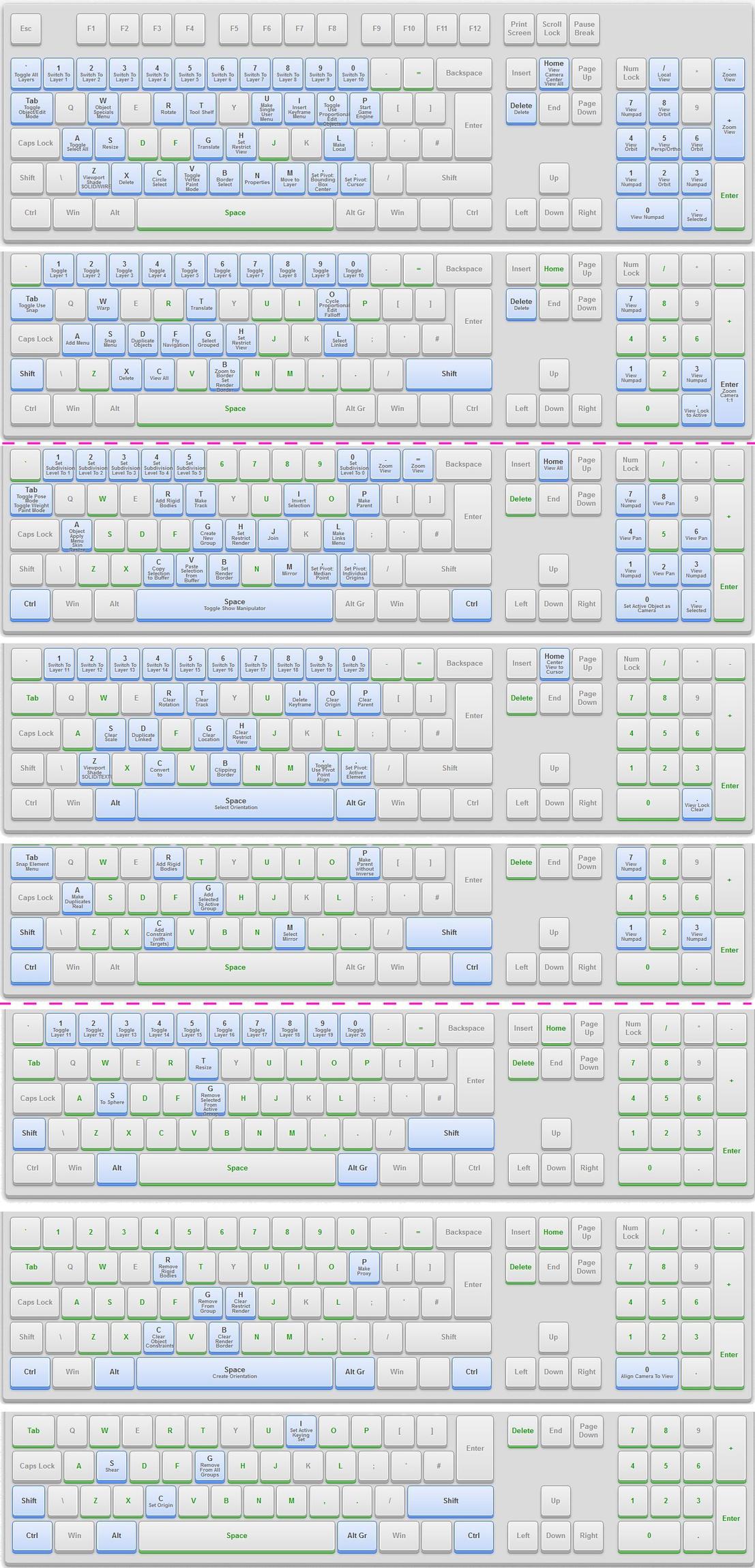
What helped me a lot, a newbie, was to get accustomed to the limited command set for modelling this. I found an interactive (shift/alt/Ctrl and combinations thereof…) keyboard reference on this webpage.
Evenbetter I screen captured all combinations and printed “cheat sheets” , now prominent on my desk as I work. In the pic below are the 9(!) keyboard combinations if anyone else finds this helpful as a jpg. I’ve printed the 9 keyboards in three landscape A3 pages - cutoffs for printing showed in dotted magenta.
Be warned I found discrepancies between keyboard layouts posted on the net, likely due to changes between revisions (?) and offcourse context! eg object-vs-edit-vs…
A couple general shortcuts I needed and not represented were: [F] for Face fill / [Shift+C] for Centering the cursor to ccs origin / [Ctrl+S] for Save / [Ctrl+Z] for Undo
I have my pen and higlighter on standby and make these corrections while highlighting the keys that I use.
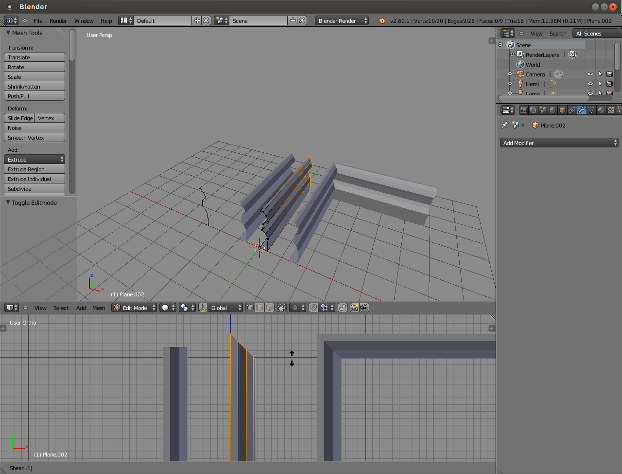
Back to the process of my learning to do the cornice and the ways about it.
yes, it’s what I was looking for - except it took me to realize what he was suggesting…
Besides being totally lost… I was interpreting Ctrl+LMB as Ctrl+letters L , M, B instead of the mouse button.
Now the Shear part of this post I understood just now understood. WOW !! the profile turns the corners. -1 for the first corner 45deg from y/ then extrude / the extrusion butt end is still slanted so -2 to turn 90deg from x and back down the y…etc…etc
Question 1: why is that with -1 and -2? the numbers seem to be multiples of 45deg, but I’m sure there is more to it…
Before I understood JA12 corner tip, I did the mitering first just manually, snapping to a grid was easy for 45deg... still rotating the butt end will come in useful no doubt.
Question 2: from the solid modellers I come from, you can rotate a face and the others remain constrained to their orientation and a new edge is formed between them and the rotated face. Can’t I constrain the other faces/edges/vertices when I rotate one?
On the more general question faces-vs-beziers, for the moment polygon faces are quite enough for basic architectural modelling like this, curves can be approximated by smoothing, before rendering.
No doubt though beziers are an interesting and powerful tool. I watched tutorials and might play with them modelling, say a car. But that’s a hobby back to architecture where I earn my $
The other question that arose is transform-vs-modify. If I modified the profile by modifying it along a path I could quickly interchange cornice profiles. However it was a little too much to handle for now.
You can’t skip beginner tutorials. They are very important to forget what you know about CAD when working with Blender.
From the top of the page where it says “new to blender?” http://cgcookie.com/blender/lessons/3-modeling/
No, shear works with the view axes and the pivot point. If you have an edge with length of 1.10 blender units, the pivot is set to median and you shear it in up/down direction 1 or -1, one of the vertices moves 0.55 blender units up, and the other one moves down the same amount.
You could change the pivot point to something else, for example
here the pivot point is set to 3D cursor (hotkey period), which is on the first vertex of the edge loop having the total length of 1 BU. Shear in up/down direction with value of -1 moves the last vertex 1BU down. Shear value of -2 would move it 2BU down, so on. If the edge loop length were 2.3 BU, shear of -1 would move last vertex 2.3BU down.
(Could also use active element pivot (hotkey alt+period) and make the leftmost vertex as active to do the same thing, but 3D cursor is more visual in an example.)
You can also switch the input order however you like. After you initialize shear or transform tool or such, you can input amount/direction/axis or direction/axis/amount and then change your mind and press the direction (-) again.
Not sure if I understand the question. That sounds like what shear does. If you mean for example how to make a smooth 90° turn for a pipe, starting from a straight edge, you could select the end, place the 3D cursor as pivot and press alt+R (for spin) and adjust the settings on the operator panel (bottom of the tool shelf, or F6).
There were no questions in those and I don’t know what you were talking about in the latter paragraph anyway.
a way to make corners of moldings is to make pieces using simple extrusion, then intersect them at a right angle. use the knife tool to cut them both at the same time at a 45 degree angle, delete the excess, and remove doubles.
Thank you.
It’s a way I tried but failed because the knife is a “freehand tool”. I was looking for a way to snap the input points to a grid or some to angles.
Didn’t find it… but it likely exists.
In general cutting with a three point plane using a snap point and to relevant coordinates would work well, for cuts.
For example with AutoCAD that would be pointing to the first point and then
2nd point: @1,1,0 (a point 1 unit in x, 1 unit in y - would be 45degrees - and 0 in Z)
3d point: @0,01 (in the z direction)
Thank you, thank you, thank you !!!
Excellent advice. That’s how I ended up modelling the cornices: Used Ctrl+LMB for the profile (snapping to convenient grid) then extruding and turning corners with Shear.
The only thing I would add to clarify is -1/1 is a multiplier of the dimensions of the face to be rotated, not BU…
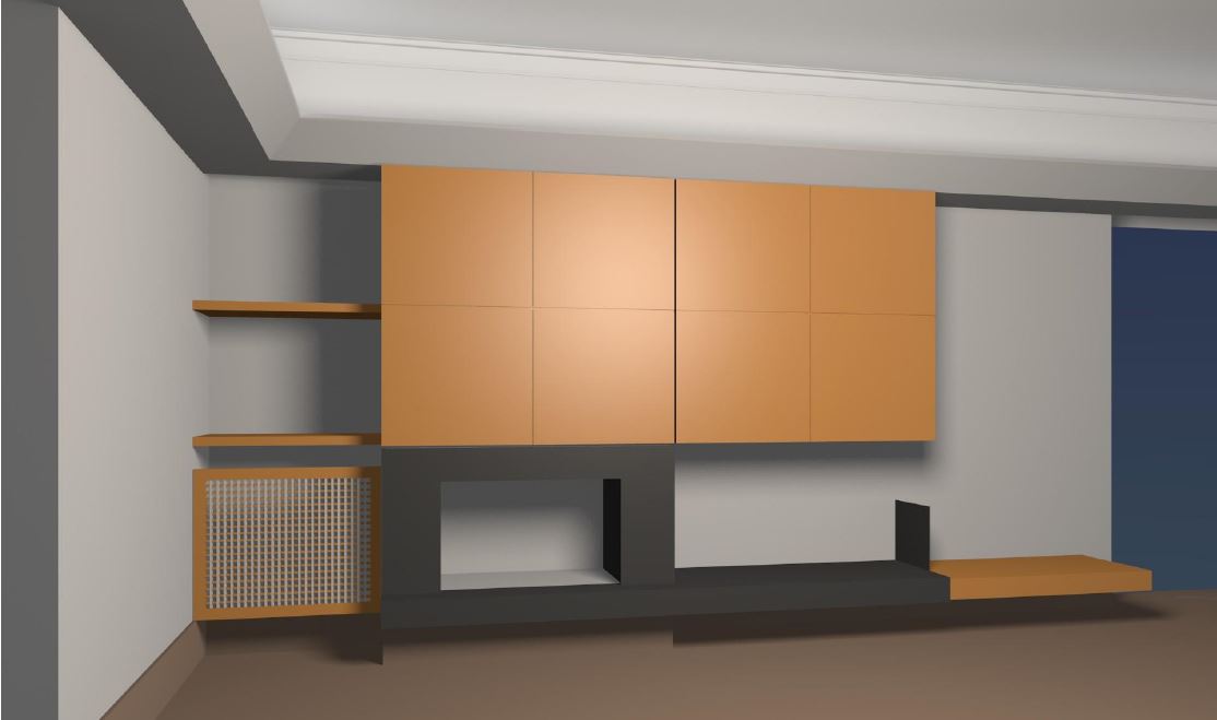
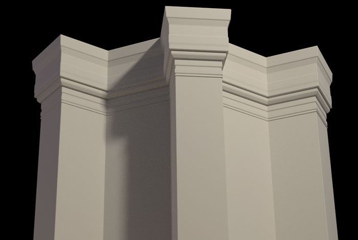
Thanks to all. Your assistance helped me produce my first model.
Here are some pictures (be kind it’s still in progress…)
No pattern mapping yet, just plain materials using solid colors.
One point light, one more with no shadows and a little ambient.
What was a nice touch was the area lights along the cornices in both directions.
Next map textures and add objects for furnishings… and windows.