I have rigged a lever clamp (basically a piston, connecting rod, crankshaft). I’ve done it with a single armature and with two armatures, both ways the mechanism does work.
But I’d like to set up limits to the rotation of the handle (essentially the crankshaft). But, in the bone IK properties panel everything is grayed out.
Could someone give me some ideas on what I’m missing or got wrong? I’m wondering if there is some detail about IK rigging I’ve just not noted in the videos I’ve watched.
So the handle/crankshaft is the controller bone for the clamp?
If so, controller bones are not part of the IK chain and can’t be limited via the IK properties panel. Use a limit rotation constraint on the controller bone to limit it’s rotation.
If this doesn’t work, post screenshots or better yet, the .blend file.
Thanks for the reply.
Here the con is IK to crank. crank is parented to control.
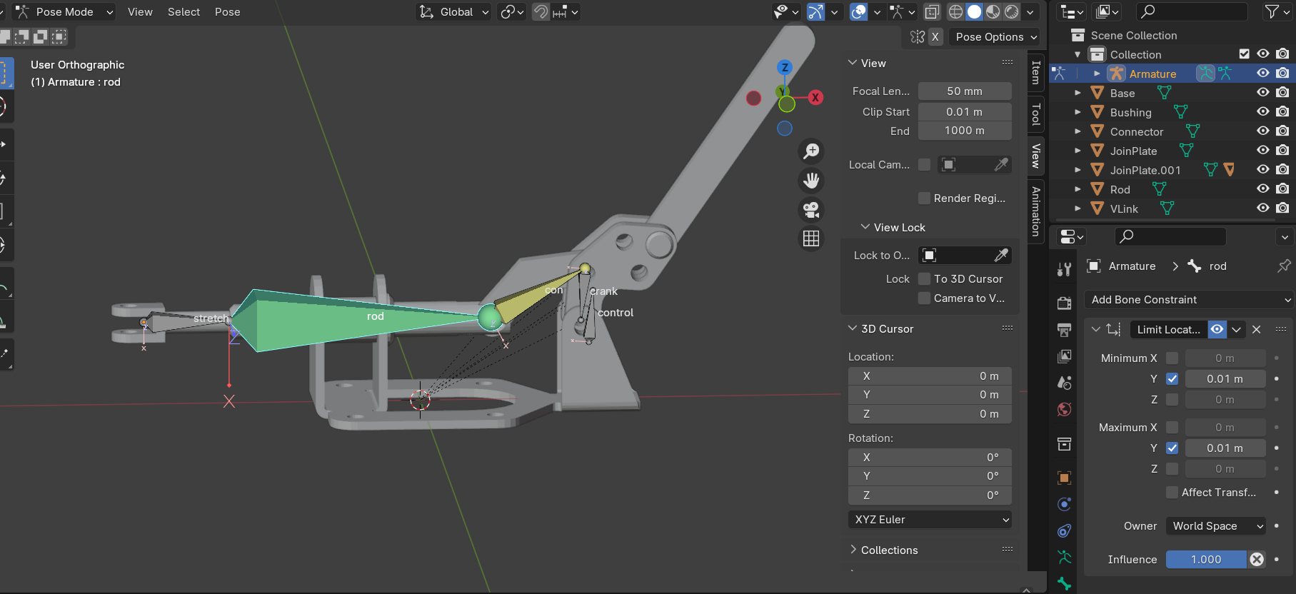
And I have a limit location on the Y of rod.
If I rotate control in the Y, the travel of rod appears unlimited.
(One problem I have is, I’m never sure when I’m referring to the bone axis or the global axis…)
If I remove the location limit on rod and add a rotation limit to control, I can’t make sense of the values or the axes. When I select the Y to be limited, the default is Min/Max = 0
And control is rotates so the tail points down.
I have not been able to make any sense of values for Min/Max. I would want it to rotate to the left about 45 degrees and right about 80 degrees. MJToggleClamp-Rigged-1-forum.blend (1.3 MB)
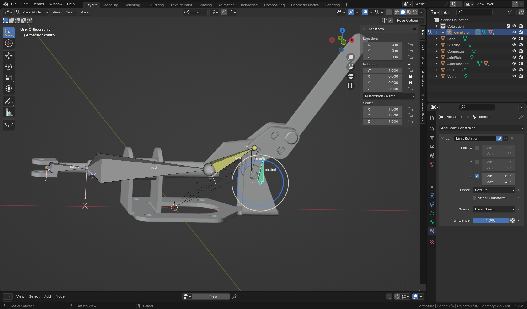
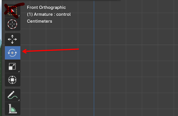
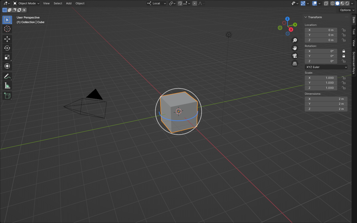
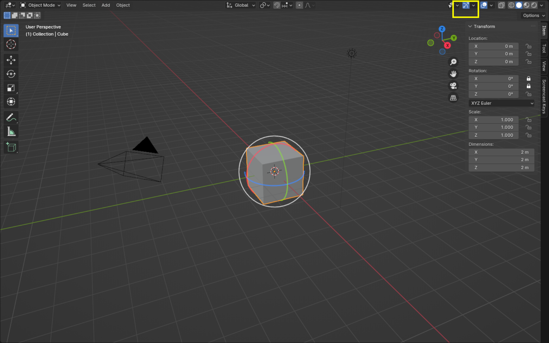
I setup the limit rotation constraint on the ‘control’ bone as you wanted. To do this, I turned on the 3d manipulator and set it to work in Local space, that way I could see the local rotation of the bone. Then I rotated the bone around, watching the values in the upper left corner of the 3d view. Entered those values in the constraint fields and set it to work in local space. I also locked down the X & Y rotations of the bone - right panel in 3d view.
I set things to work in local space, not global, so it would work in any orientation. If it was set to work in global space, it would work fine as is, but would fail if the armature object, in object mode, was rotated 90 degrees. You see, as is, ‘control’ rotates on the global Y-axis. If the armature object gets rotated 90 degrees, now the bone would rotate on the global (or world’s) X-axis and the constraint wouldn’t work.
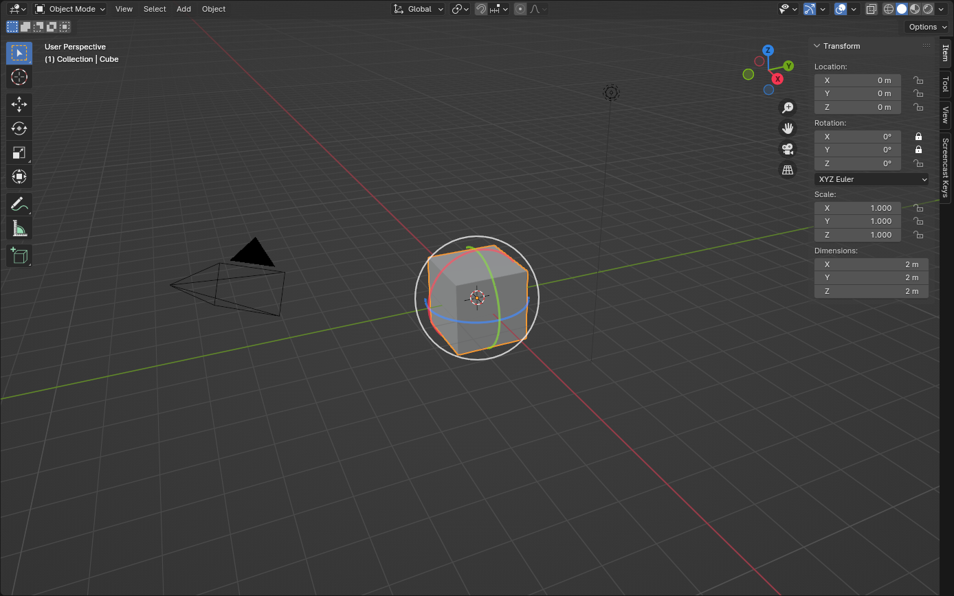
The 3D gizmo is set to work in local space and the X & Y rotations are locked down. Since the bone can only rotate on it’s Z-axis, only the blue circle appears. Unlock the X-axis rotation and a red circle will appear too.
And I have only the blue circle because the cube can only be rotated on it’s Z-axis. Unlocking more rotation channels will give me more circles, like red for X-axis, etc…