I am having a problem with “stretching” of several imported images I am layering together to use as a texture.
Let me set the scene:
I have several separate wall objects. Each wall has the height (X), but different lengths (Y).
I have two seamless images I have imported to use as a texture. The “bars” have an alpha so can see through them; and they both have different fiddly values such as hardness, ect.
-I do not wish to flatten these images into one image via GIMP or Photoshop or the like…in addition to the different spec/hard/etc, it is much faster to just load/layer on another texture image/bump map/etc than try to rebuild it each time in an image editor.
In the material node editor, the images from (2) are layered on each other via material nodes.
The Y variable is fine. The issue is with the X. See following picture as an example. The upper right is the correct, unstretched version. However, when it is applied to the other walls, they stretch.
For my actual project (this is just an example for here), I want to just define the texture as is, then have the program tile it appropriately. I’ve fiddled around with various settings, and while I’ve had some interesting results, none of them are what I want. There’s more than likely something very simple I’m overlooking that I can add to my node view, else a button to push elsewhere, but I just can’t seem to find it.
5a. Side note: if I could somehow convert my two material nodes into a texture node (without losing the versitility in (2)), then I could use geometry/mapping nodes to get closer to what I want…there are still /other/ issues, but the stretch factor is solved.
The best way I can think of to accomplish what you want is to use an “Object” type as the map input. This will allow your geometry to slip underneath the texture coordinates, instead of stretching. Use an Empty as your UV object. Make sure to use “Cube” map type to get nice projections on perpendicular surfaces.
(Apollos: you mean like some of the decal tutorials that are out there?)
(PapaSmurf: Repeat already enabled, along with mirror. The bars texture is actually only one bar, which has then been repeat/mirror to create the initial pattern I wanted)
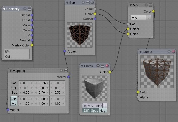
Okay, after fiddling around in the material nodes, I finally came up with the following:
Better, except there is still a wee little issue. Upper right panel is the desired condition to be tiled. Lower wall and upper left wall have the new material mixture applied. As can be seen, the material seems to be “continuing” in the interm space between wall objects, not “restarting” when applied to each object separately. Here’s a screeshot of the current material node flow that I am working with. Changing to anything other than “local” in the geometry under the current node flow makes for…let’s just call it ugly and/or plain wrong.
That’s a side effect with Object input I suppose. You might end up having to UV map, and scale the UVs for each section to avoid it. Maybe PapaSmurf has other ideas…
EDIT: UV mapping is simple enough with a plane object like that.
As a matter of fact, if you UV mapped one segment, then duplicated that segment for each piece you needed, it might work. You could even duplicate and join in Edit mode, if Object mode wasn’t good enough.
I have thought UV mapping and duplicating, except the walls in question for the actual project are of different lengths and so forth and so on; and I just want to be lazy and throw on the built texture.
So, no secret-special-squirrel buttons to make it work, eh? I can’t make the texture “start over” given my current material settings each time I apply it to a new object/mesh?
I suppose I can make copies of the texture each time it doesn’t fit, then fiddle with the mapping for that copy until it meets my needs. Not a perfect solution, I admit. Maybe I’m just making a personal wish list for what I want in future Blender updates.
Until there’s an object level Size and Stretch, I think you’re stuck with UVing, unless you want to make a new material for each part that needs different mapping.
map input image to Global Cube coordinates. ofs Y 0.5 if u want top edge to align when the object/plane center is not an even BU coordinate. kinda works, but your nodes are more elegant.