Hello! I’m very new to blender, coming to it to create some models for 3d-printing.
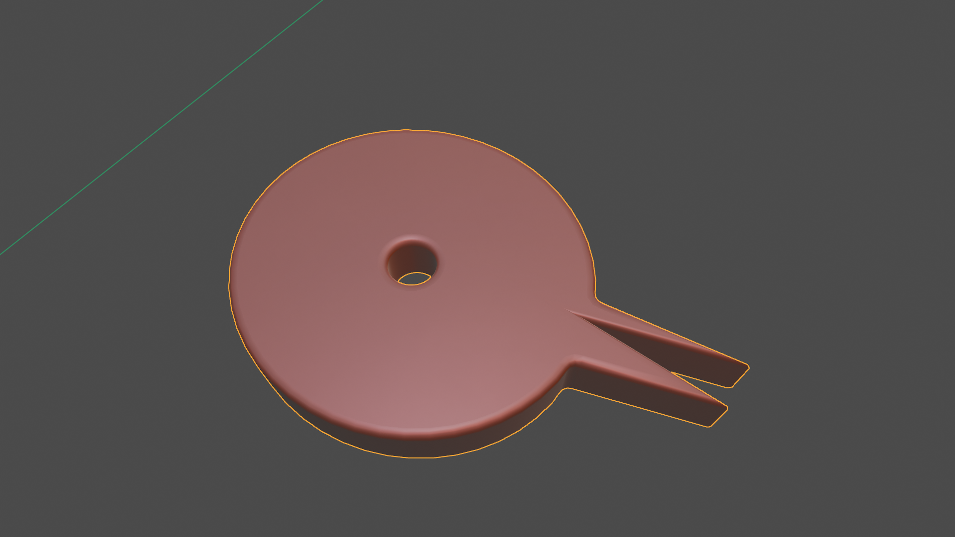
I have this shape as a svg-file (see “1”, I’m not allowed to post multiple images so I merged them to one image).
And want to extrude and bevel it like this (view from the side, see “2”):
How is it done? I already tried 2 things, one as a curve and another as a mesh, both results where not very good.
So I removed the filling from the svg (found that this gives odd vertexes inside the object), imported the svg via File → Import → .svg. I went to “Object data properties” → Shape → 2D
→ Fill mode: Front
→ Geometry: Extrude 0.008m
So far it looks good (See “3”).
→ Bevel: Profile, Depth 0.004m
This seems to enlarge the object, removing the gap between the 2 spikes in the right bottom corner, which I don’t want (See “4”).
→ Trying it with Bevel: Profile, Depth -0.004m
Nope, thats also not what I want (See “5”).
Any idea on how to achieve a bevel which doesn’t enlarge the obejct?
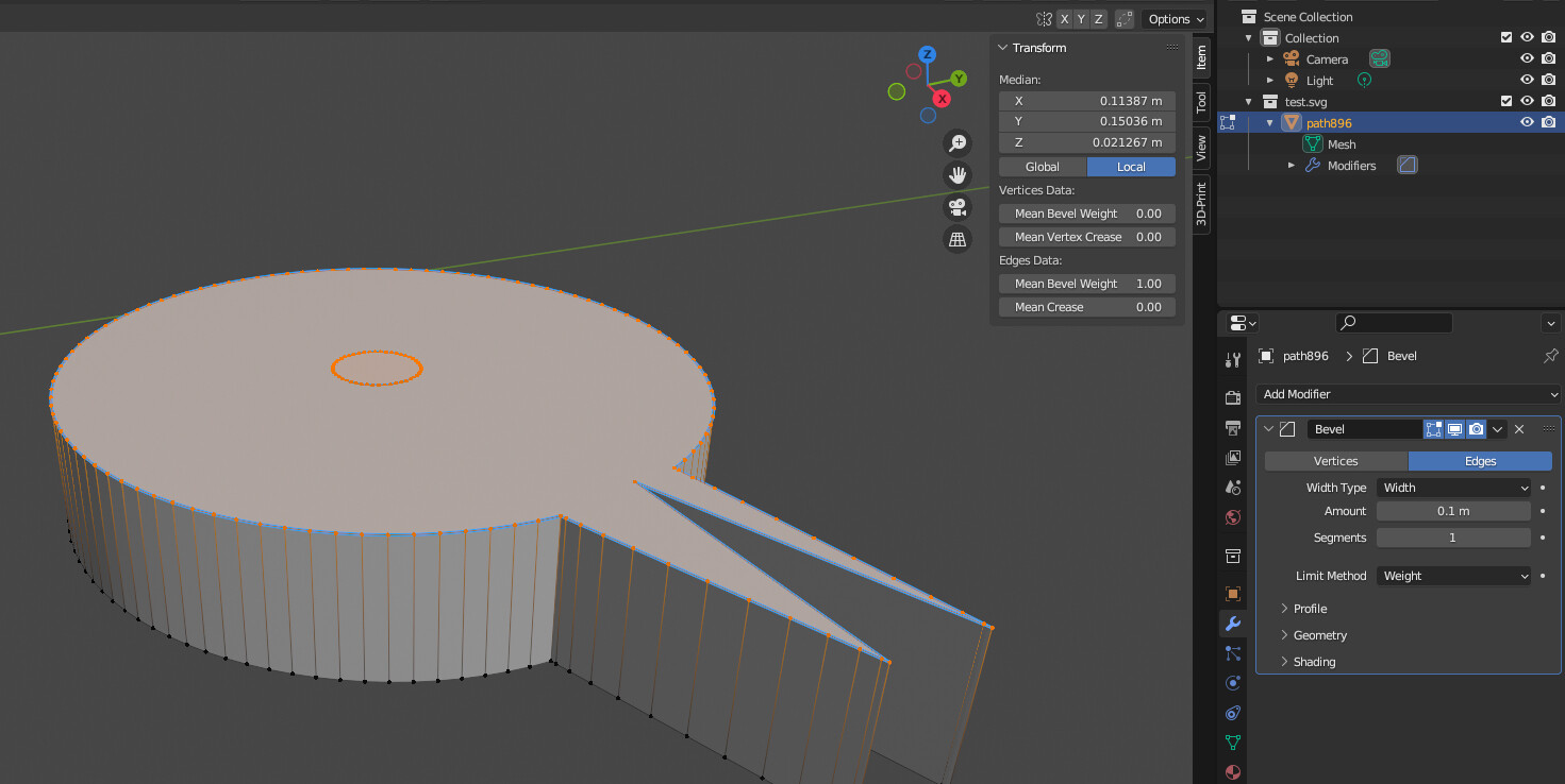
The other thing I tried was to import the svg and convert it to a mesh.
In edit mode, I pressed E and Z, to extrude it in the z-axis (See “6”).
Now I’m here, but I don’t now how to continue. I select “Bevel”, but it seems no matter what I’m doing then nothing is happening.
You can’t really bevel an edge that’s only adjacent to one face on one side.
In case of “6”, you could try to hit “I” to inset the shape first, and then hit “F” to close it, since you wont need to worry that much about ngons as long as they’re planar.
Then, you could bevel the old top edge selected in “6”, which would now bevel correctly given it has faces on either side that it can bevel “into”.
it is VERY IMPORTANT to apply the scale of the object (in object mode, press CMD/CTRL+A and choose scale), or else the bevel will give weird results. Same goes for the bevel modifier.
Another approach would be subdivision surface modifier on it, and working with edge loops, but then you have to figure out what to do to the ngon, “Grid Fill” might not be enough.
Point being, when you subdivide anything other than tris or quads, things are gonna get weird quick.
Just my 2ct, hope it helps.
PS small correction, you can’t hit “I” to inset because it’s not a face yet. So, either press F to create an ngon and inset that (which will scale down the inner edge more conformingly to the shape) or press E and then S to extrude and scale down, will probably cause problems with the pointy area.
Thanks again for your reply. I’m sorry, I still don’t get it to work
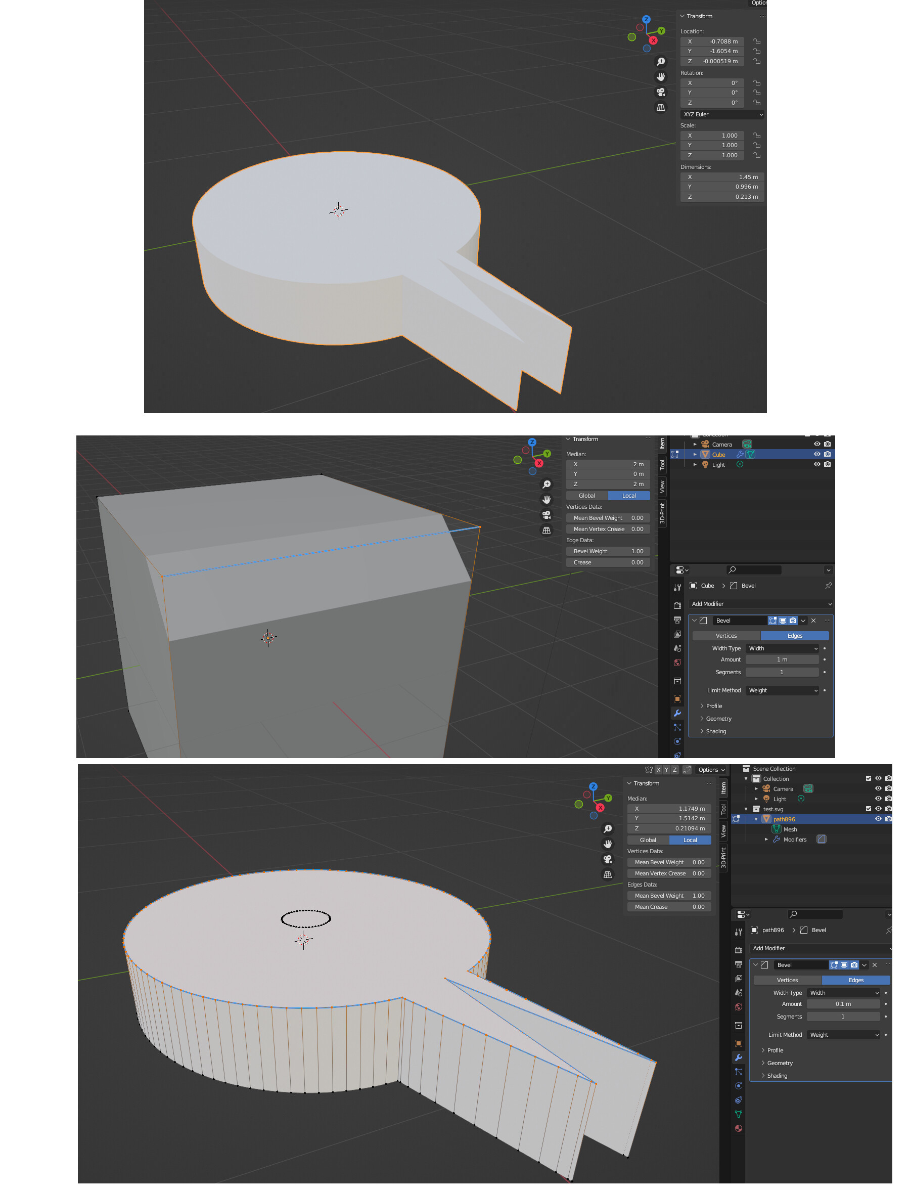
The scale of my object already is 1/1/1, but nevertheless I did a CTRL-A → Scale (1st image).
But while a bevel on a cube for example is working as expected (2nd image)
just nothing is happening on my imported svg (3rd image).
Is the way I’m “filling” the object wrong perhaps somehow? I just select all top-points and press f to get a surface at the top. I know I will have to boolean-remove the hole in the middle, just wanted to get the bevel to work.
Check Face Orientation to make sure that the Normals are not upside down.
(If there is a problem, it will be displayed in red. In this case, select all with and correct it with Shif+n.)
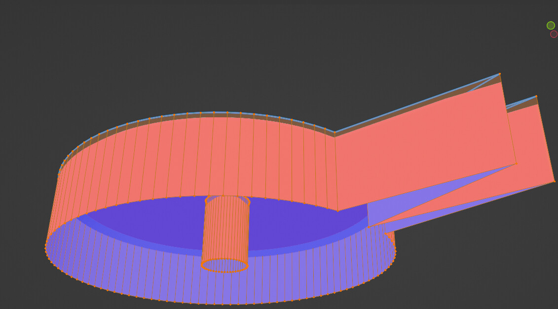
Just one question concerning the Face Orientation/normals: When turning “Viewport Overlays → Face Orientation” on, every face oriented “down” and “inside” is blue, and every face oriented “up” and “sideways” is red:
Pressing Shift-N, the colors just swap. So no matter what I do, I got red faces somewhere. It doesn’t seem to influence the bevel, so I’m fine with it, just to be sure: Should I do anything with the normals? Would you prefer the red faces at the top or at the bottom?