night !
is it possible or you just have to use standard textures stuck on ?
Excuse me but I have no idea what you refer to as CIE.
You can use procedural on anything with limits.
You can Bake out that Procedural to Texture Maps and add those…You can paint Texture Maps and apply…
You can use the Grease Pencil and paint a canvas…
???
thank for answering !
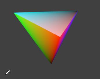
the cie is the diagram referencing all the wavelenght in the standard spectrum.
the thing is how to make the gradient of the primaries meeting in the central white point like on the diagram above ?
I’m not sure how you could set this up in a shader, but in your Color Management > Sequencer there are 2…
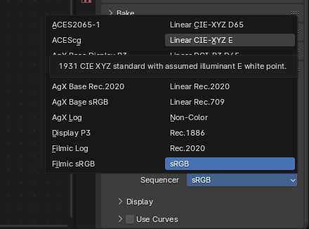
D65 and E
Depending on how Math knowledgeable you are you could replicate the Formula
this does not allows to bend the color gradient arount 1 point on the surface object, it jus changes the output color space of the render.
check the reference image in the screenshot above : thats the texture to get.
is it possible to get this texture on a flat plane for instance with procedural, or you have to use standard textures ?
I understand. I know what you want…I just don’t know how you would get a Color Space Function into a Material Shader…That is why I suggested you replicate the Formula to see what happens if it is applied, perhaps to a light.
Vertex paint does something like this;
I am not sure how you could map a colour ramp in that way in the shader editor.
I do suspect that if you can map a colour ramp the resulting colours would be something like those (not the same as your image).
Cycles is not a spectral render engine, I do not think rgb will give you those nice spectral gradients. I do not really know if a spectral engine would do better but it might.
Tweaking saturation does not give a nice gradient (RGB curves will also tend to clip)
Your best bet is to UV map an image texture.
Hi,
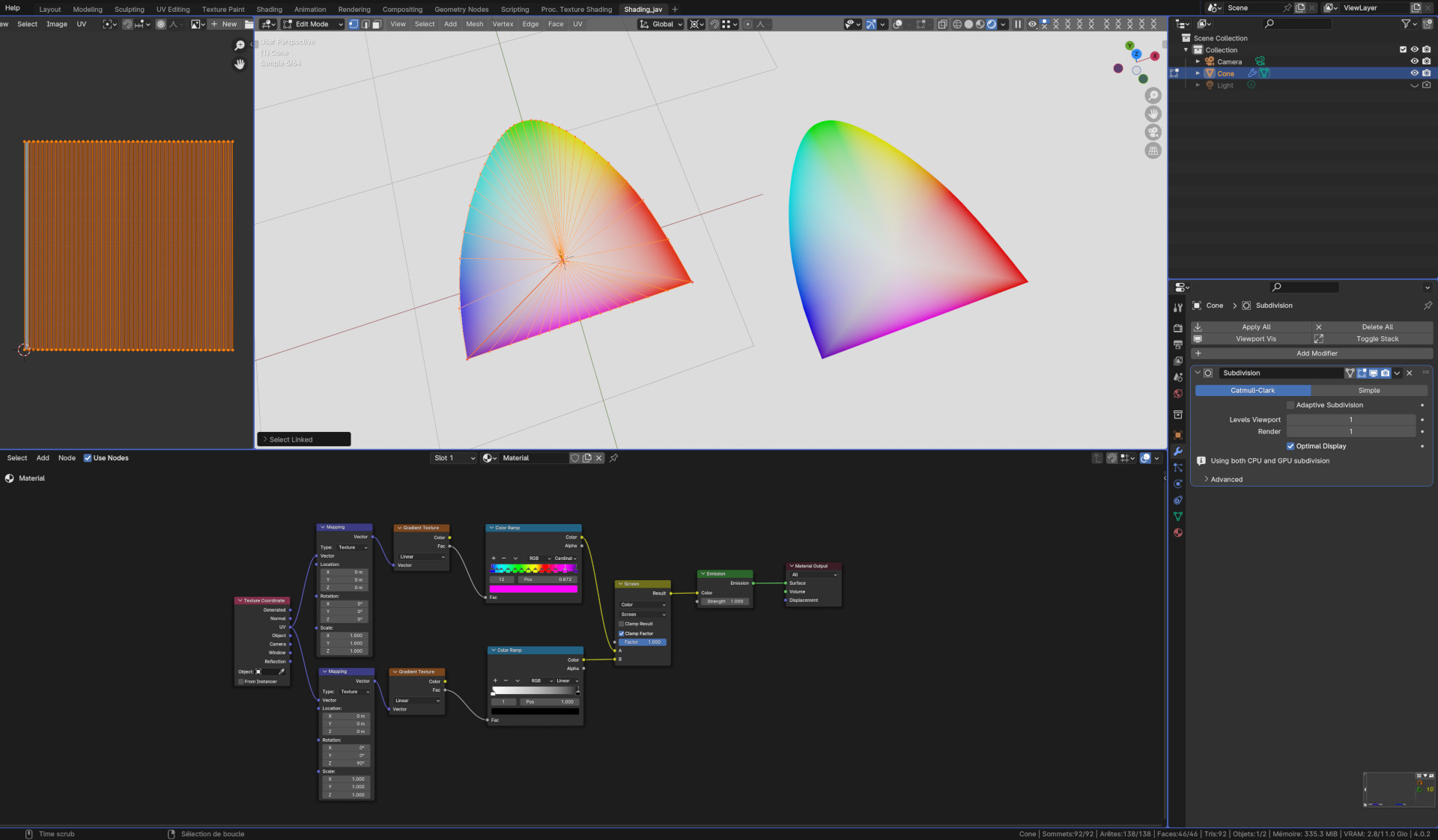
This is not colorimetrically, geometrically nor mathematically correct…
But this could be a start.
@DNorman, ok copy about concerning the spectral render angine, trying you way checking what it could come out and like you said, last solution, uv mapping…
could uv mapping work for volume by the way ? if having to introduce depth for luminance [0, 1] in the cone down to up ?
also do you know which spectrl engine could be used to create textures like this ?
trying your nodes.
@JaAlVir657, ok trying your nodes as well, no issue if it s not perfectly accurate.
@DNorman , @JaAlVir657 , thank for your answers, processing with your usefull details.
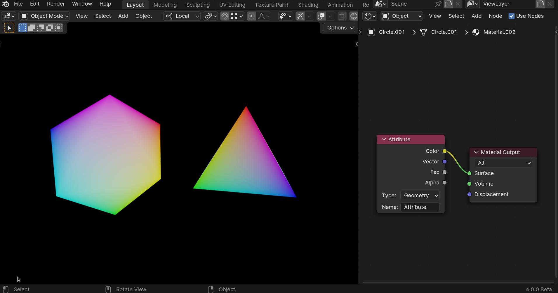
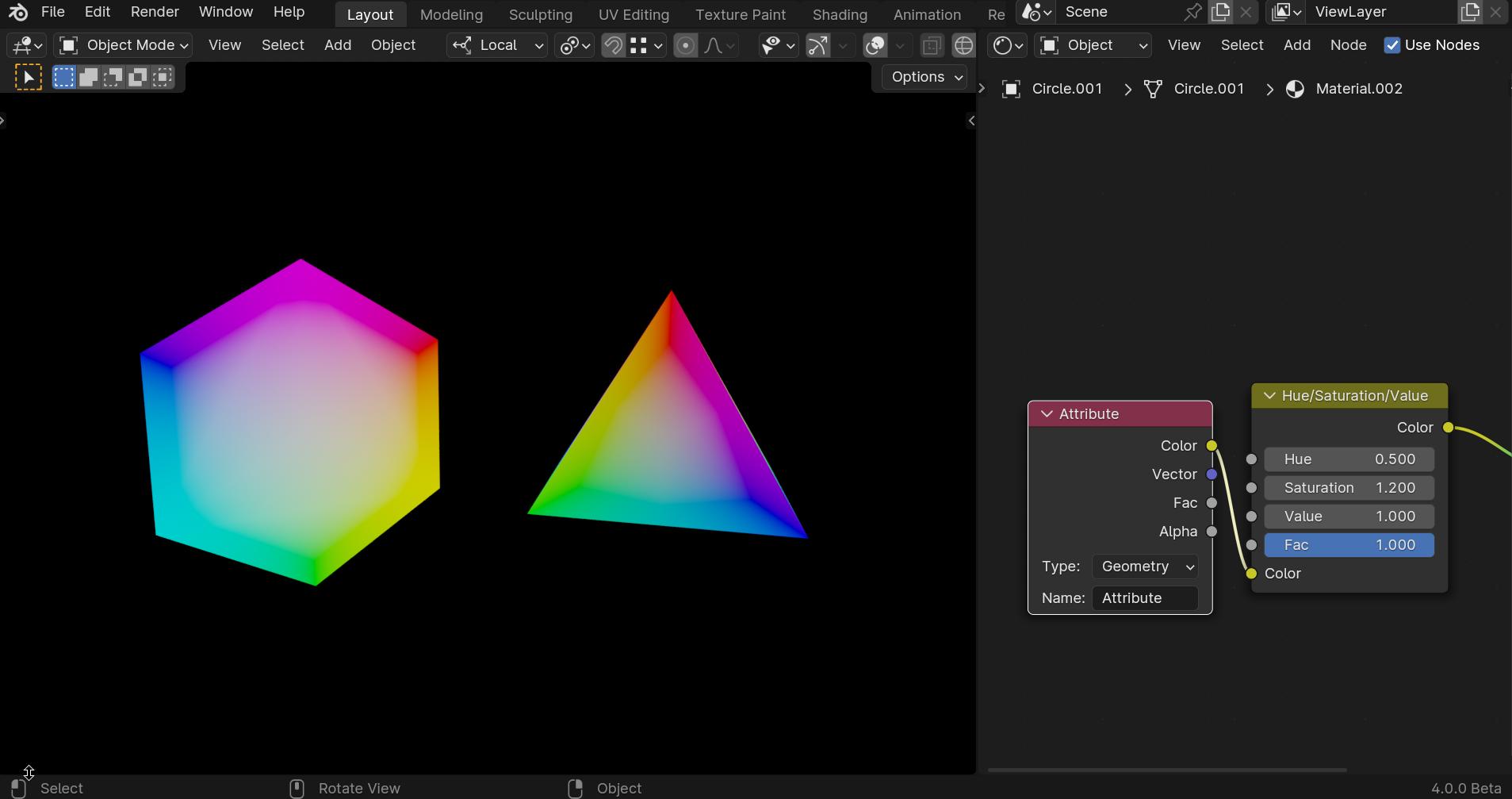
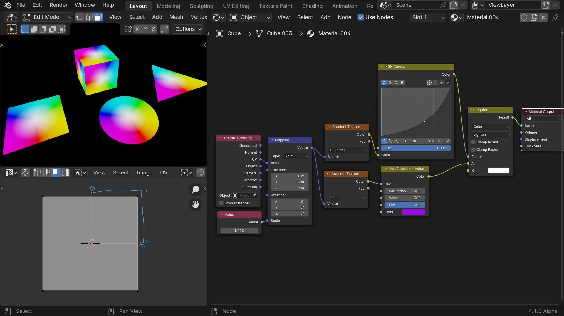
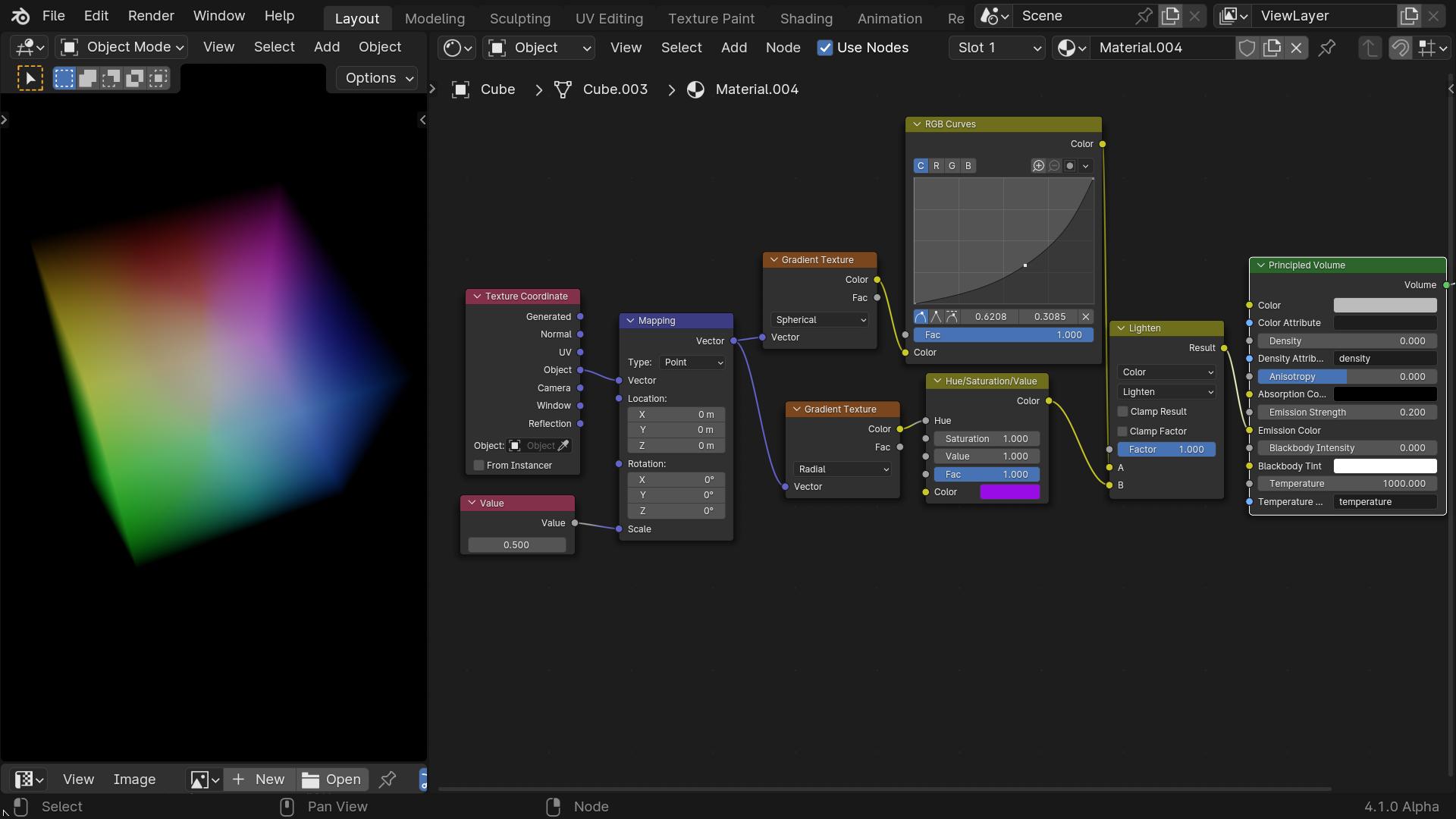
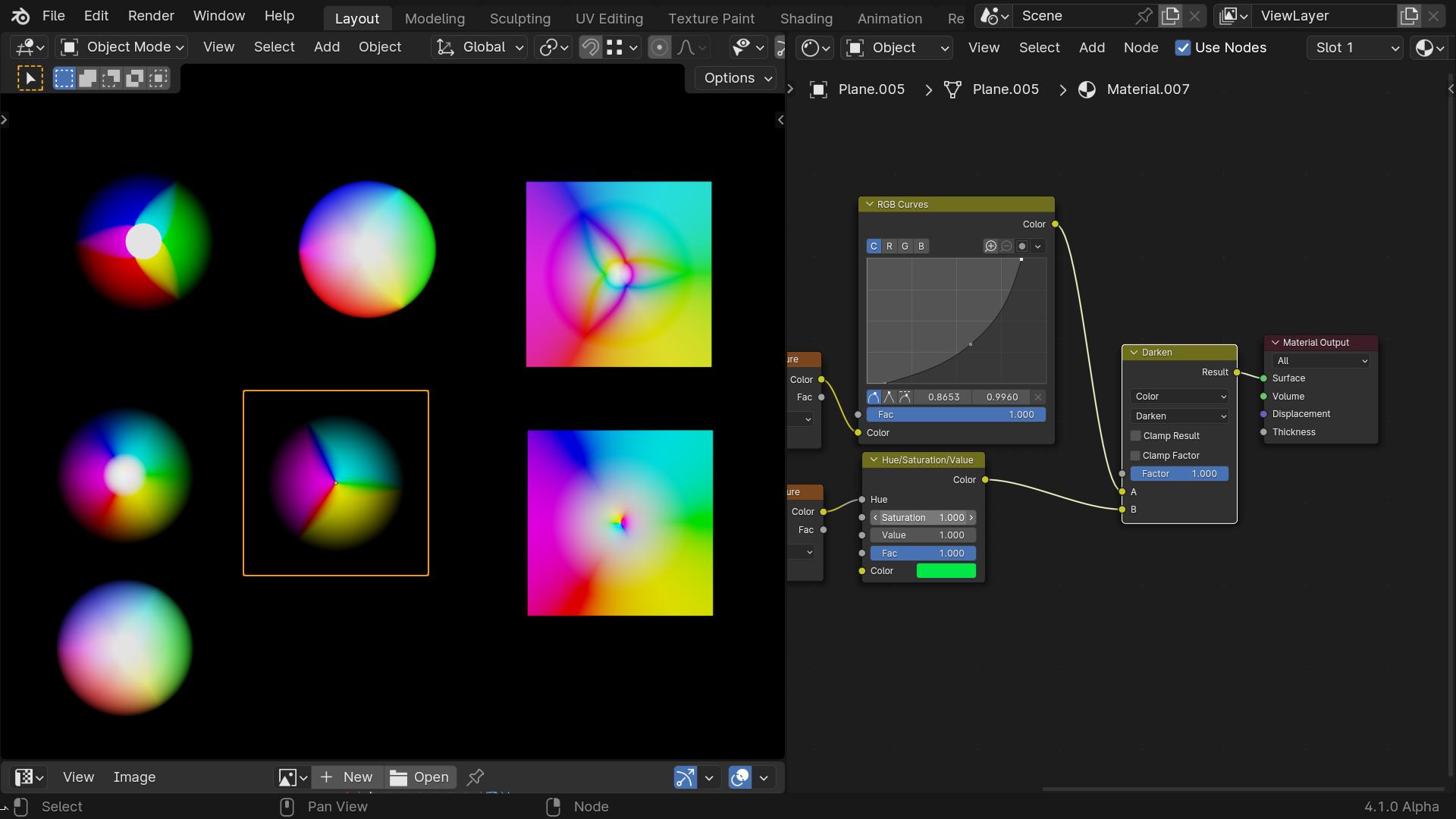
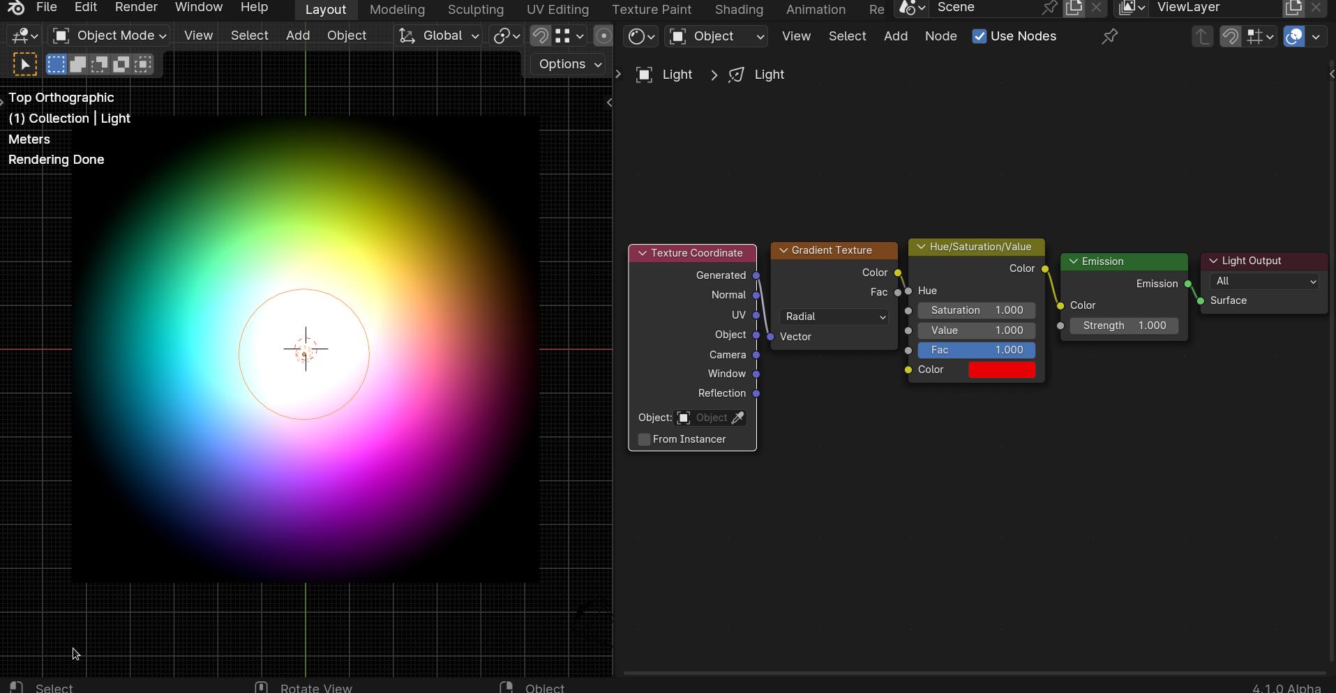
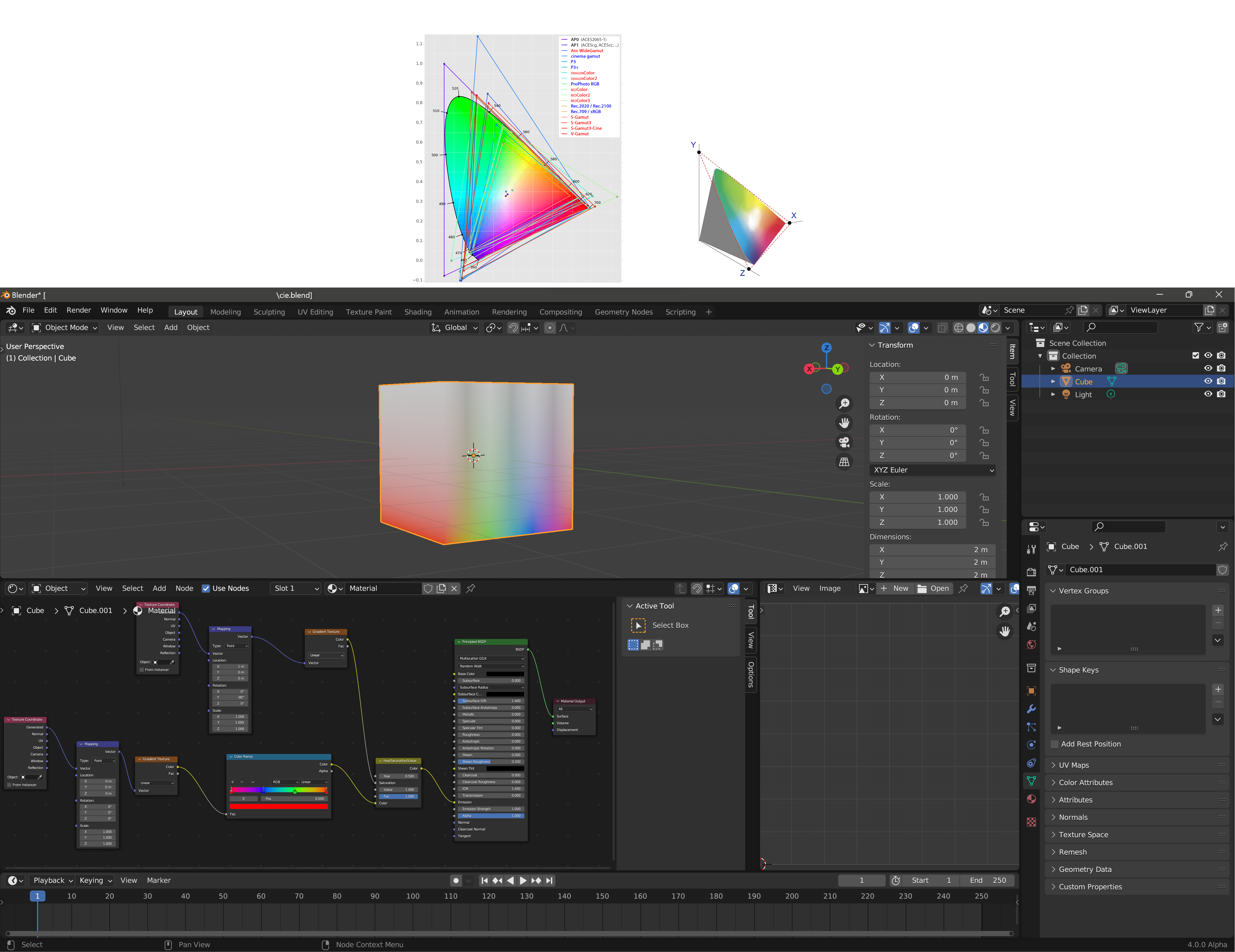
I found one way of doing something similar with just nodes;
The Planes (square, triangle and circle, use object cords) and the cube uses UV’s
The uvs are all centered on 0,0 (to make it easy to scale.)
You can use the mapping scale to scale the white, the colour curve to alter the gradient a bit.
I used the HSV (Hue) because it will “wrap” the colours - with a colour ramp there was a seam due to the radial gradient.
If you change the colour of the HSV the colours will rotate.
No UV mapping will only map to surfaces, you have to use object or generated for volume.
Also it is fun to try out the different colour mix settings ![]()
Edit: Last one (I promise) I played with the values and viewing angle of the emission one to get it looking better. ![]()
Edit 3
you knew I could not resist another!
No I only use Blender, I do not know if would help although I do suspect that it would handle the transitions better. Whether you could find a way to map them I have no idea.
I am aware that my last experiments were not really mixing the colours but they were fun. The only method that was truly mixing/additvly them was the vertex paint one.
@DNorman, thank for your work and your efforts on the question !
ok copy !
very interesting points implementing and and processing with everything you just presented !
also if it s not too much to ask ![]() :
:
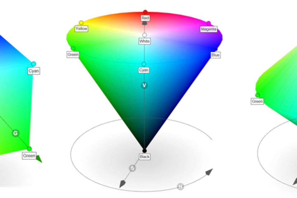
do you know how it would be possible to represent a triangle like you have above but in addition to the all color gradient with the 1 point in the middle of the top surface, another luminance gradient going through the volume from the bottom of the triangle (where the blacks are) to the top of the triangle (where the highlights are, max color value) :
like this one but with your triangle for instance :
an interesting thing would be that the middle of the volume follow the withe point luminance and all the colors progressively follows their radial luminance more and more outward the triangle until they reach their max saturation on the spectrum.
like that the texture would represents all the colors values on the spectrum so all saturation and luminance.
ok copy, yes it was just for information ifthere was spectral engine existing.
no issue anyways your solutions are excellent, it s enough for the current application.
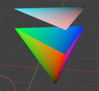
Sorry my screenshot was not to clear, the vertex paint triangle is actually a pyramid, so you could make a three sided one and paint the top vert black and the bottom corners RGB
(colour management is set to standard none.)
not sure about the volume for this one. Vertex paint attribute colour does not seem to work with volume (probably because volume does not have verts)
Edit:
It occurred to me to use lights and light nodes, this is not really what you are after but it is the closest thing to seeing the whole spectrum in one face I have come up with.
@DNorman, nice, thank !
trying everything you presented and coming back to you if necessary !
evening !
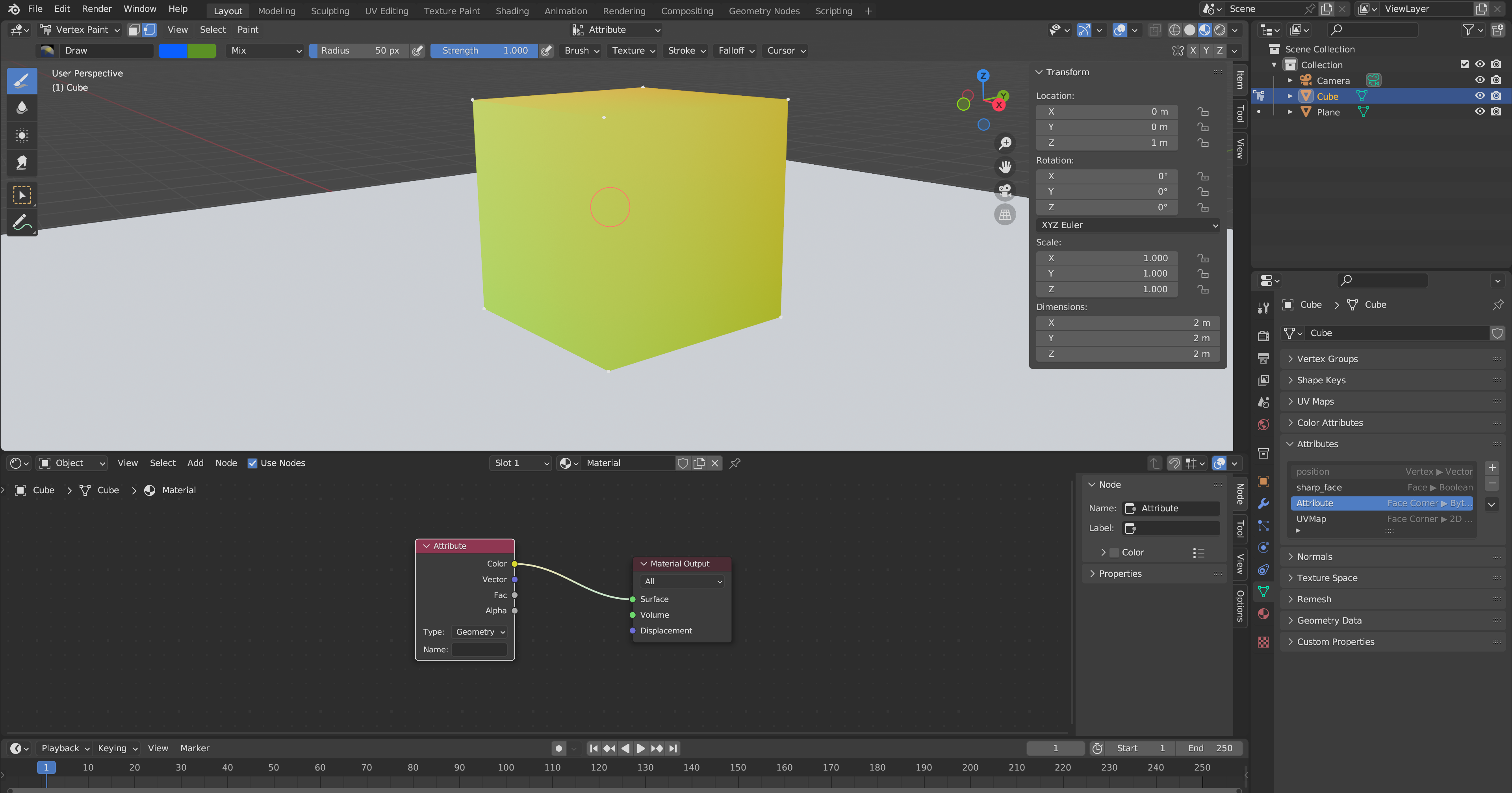
@DNorman, how do you make these gradients with vertex paint ?
with the feature in data tab and vertex paint mode ?
what is it ? you paint them and you put them in the ‘Attribute’ group ?
how do you give it as a reference for the procedural texture to be applied to ?
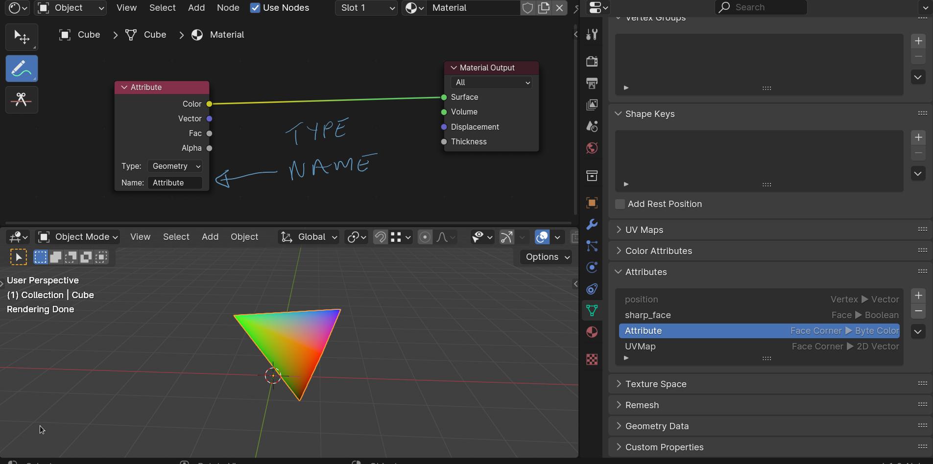
You are very close you just need to type the attribute’s name in the attribute node in the texture editor.
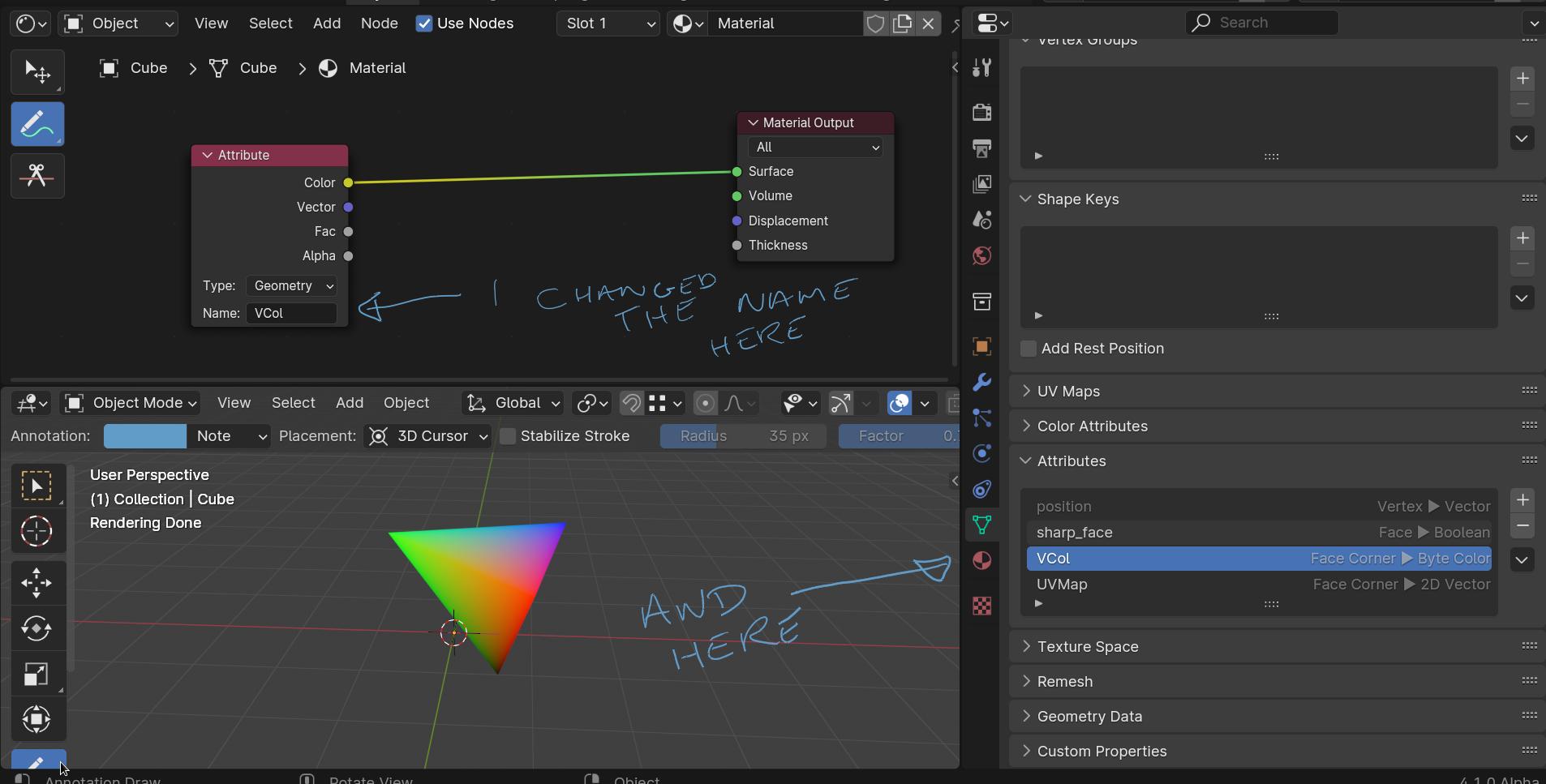
It is a bit confusing because by default the name is Attribute (they could have called it “face corner colour”). You can change the name in the attribute tab (mesh properties) click on the name and type a new one, but you would have to change it in the shader editor node too.
You may have noticed that the Atritbute type is face corner (not Vertex colour) all the faces that use that vert are influenced when you paint. But it is possible to have faces that use different colours.
If you separate a face in edit mode and pull it away from the others, paint the verts in vertex paint mode.
Go back to edit mode, put the face back where it was and merge by distance
This is just to show you why it is a “face corner” attribute, vertex paint does not really paint the vertexes - it paints the face corners!
Edit:2 (sorry I wrote on the phone and it was terrible)
The attribute is automatically created,
I do not paint the gradients. Vertex paint mode assigns colours to the corners of the faces, just paint one vert red one blue etc and the gradients appear as a result of the colours blending.
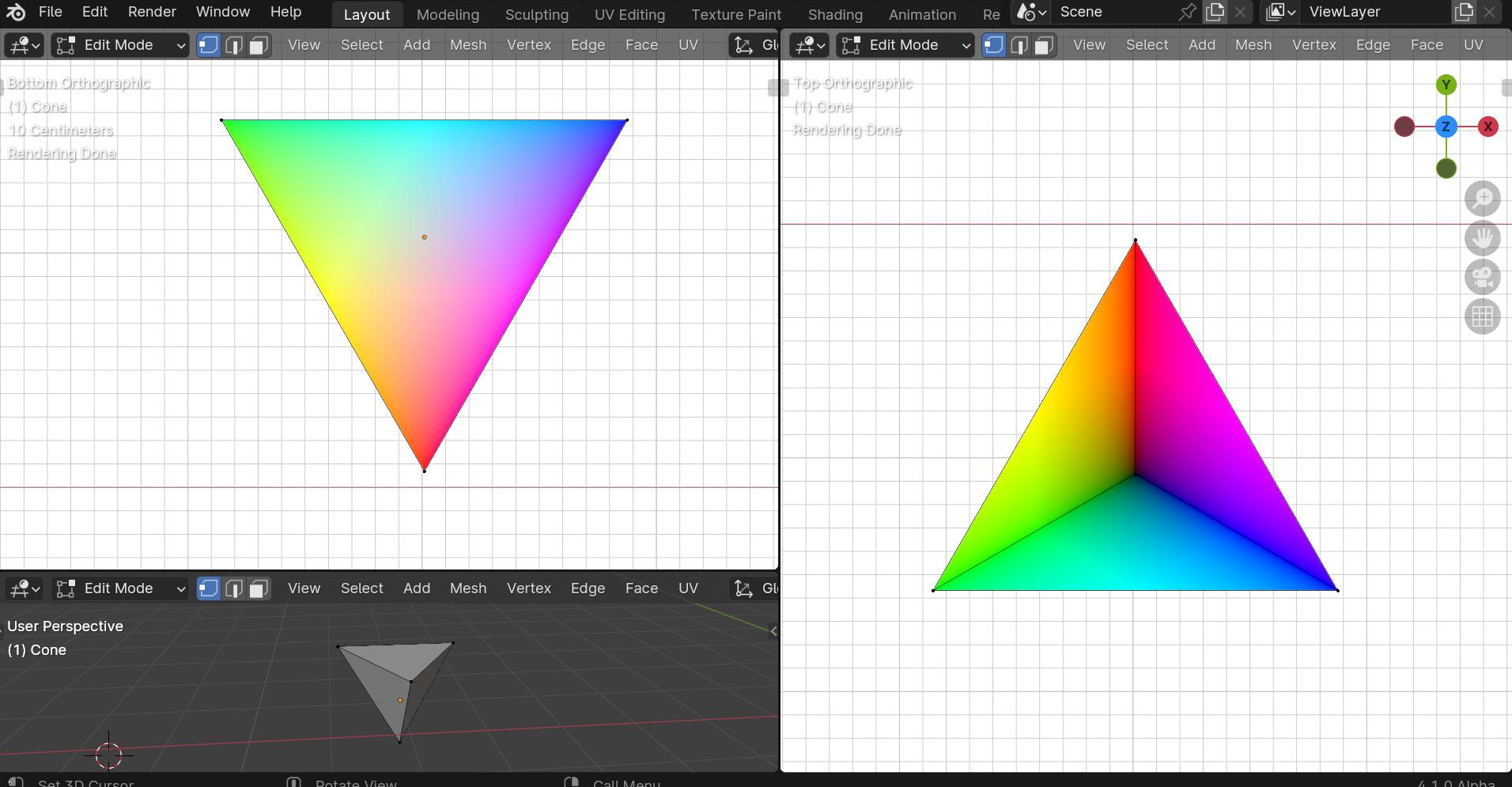
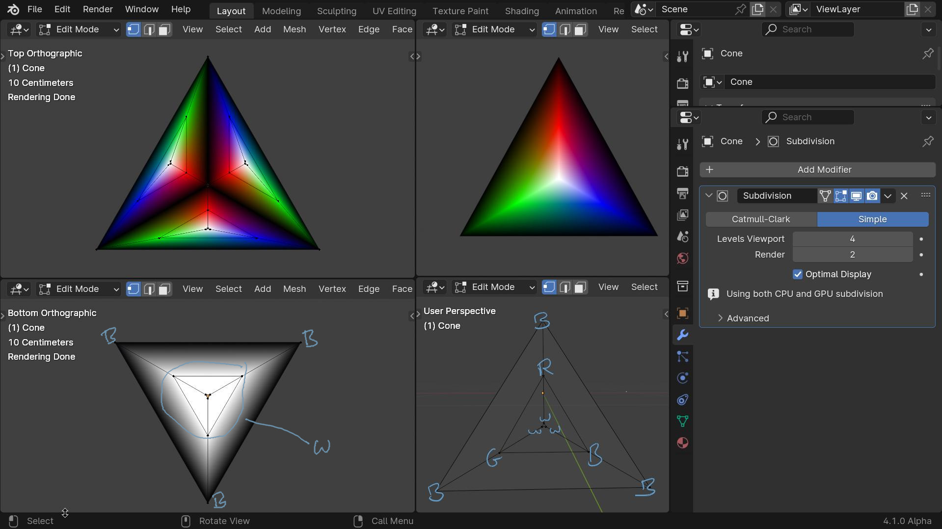
As you brought this up again I have a new one. This is vertex paint, I inset-ed the faces and painted them as in the notations.
The subdivision (simple) is needed to help blend the colours nicely.
Now the whole spectrum on each face. It is a 3sided pyramid (grey-scale underneath)
![]()
@DNorman, thank for your quick and constructive answer !
quickly checked your answer, but definitely will process all your usefull informations as soon as possible !
coming back after it !
![]()