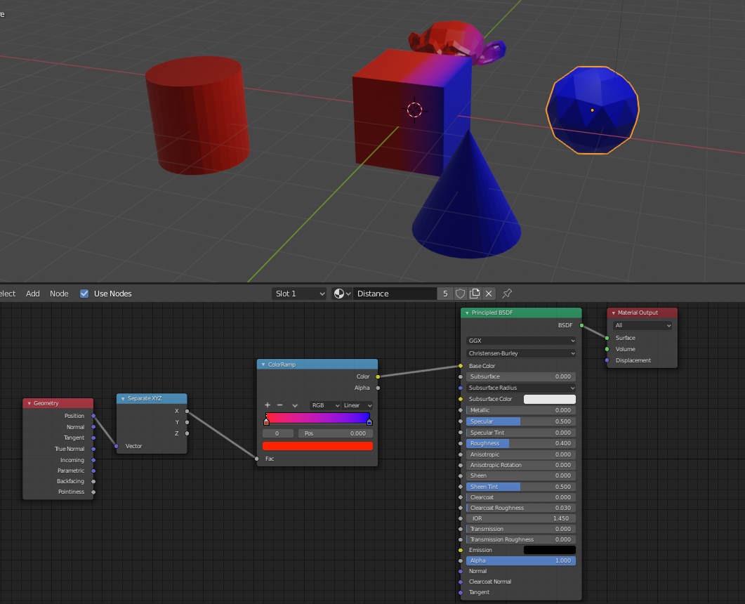
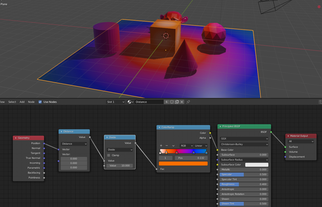
That’s not so straight forward as it seems… You can use the AO node, but it will use the median distance from hit points. You probably want the minimum distance instead, and for that we don’t have any specific node.
However it’s possible to use OSL for tracing rays and use the minimum distance…
void rng_seed(output int rng, int seed)
{
int chash = seed;
if (chash == 0) chash = 1;
rng = chash * 891694213;
}
float rng_uniform(output int rng)
{
float res = rng / float(2147483647) * 0.5 + 0.5;
rng *= 891694213;
return res;
}
void to_unit_disk(float x, float y, output float x_out, output float y_out)
{
float r, phi;
float a = 2.0 * x - 1.0;
float b = 2.0 * y - 1.0;
if(a > -b) {
if(a > b) {
r = a;
phi = M_PI_4 *(b/a);
}
else {
r = b;
phi = M_PI_4 *(2.0 - a/b);
}
}
else {
if(a < b) {
r = -a;
phi = M_PI_4 *(4.0 + b/a);
}
else {
r = -b;
if(b != 0.0) phi = M_PI_4 *(6.0 - a/b);
else phi = 0.0;
}
}
x_out = r * cos(phi);
y_out = r * sin(phi);
}
void make_orthonormals(vector N, output vector a, output vector b)
{
if(N[0] != N[1] || N[0] != N[2]) a = cross(vector(1, 1, 1), N);
else a = cross(vector(-1, 1, 1), N);
a = normalize(a);
b = cross(N, a);
}
vector sample_cos_hemisphere(vector N, float randu, float randv)
{
vector T, B;
make_orthonormals(N, T, B);
to_unit_disk(randu, randv, randu, randv);
float costheta = sqrt(max(1.0 - randu * randu - randv * randv, 0.0));
return randu * T + randv * B + costheta * N;
}
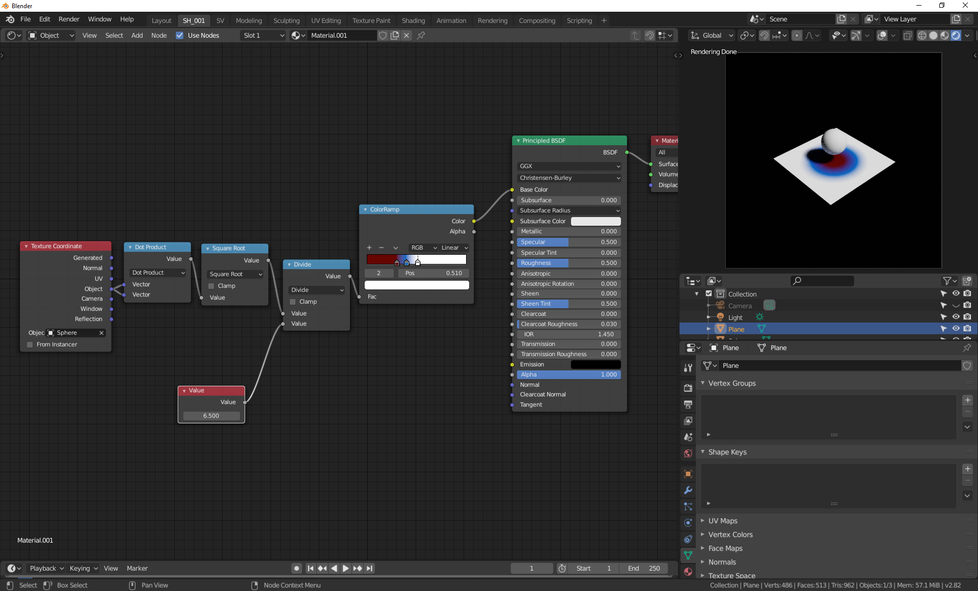
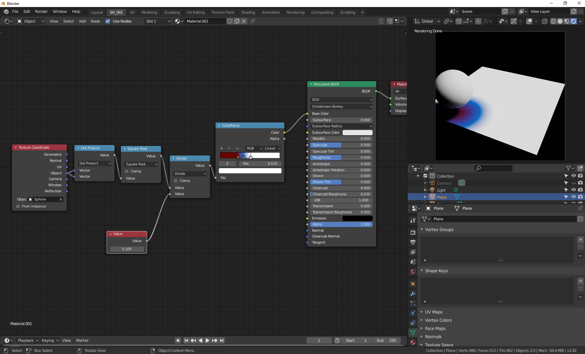
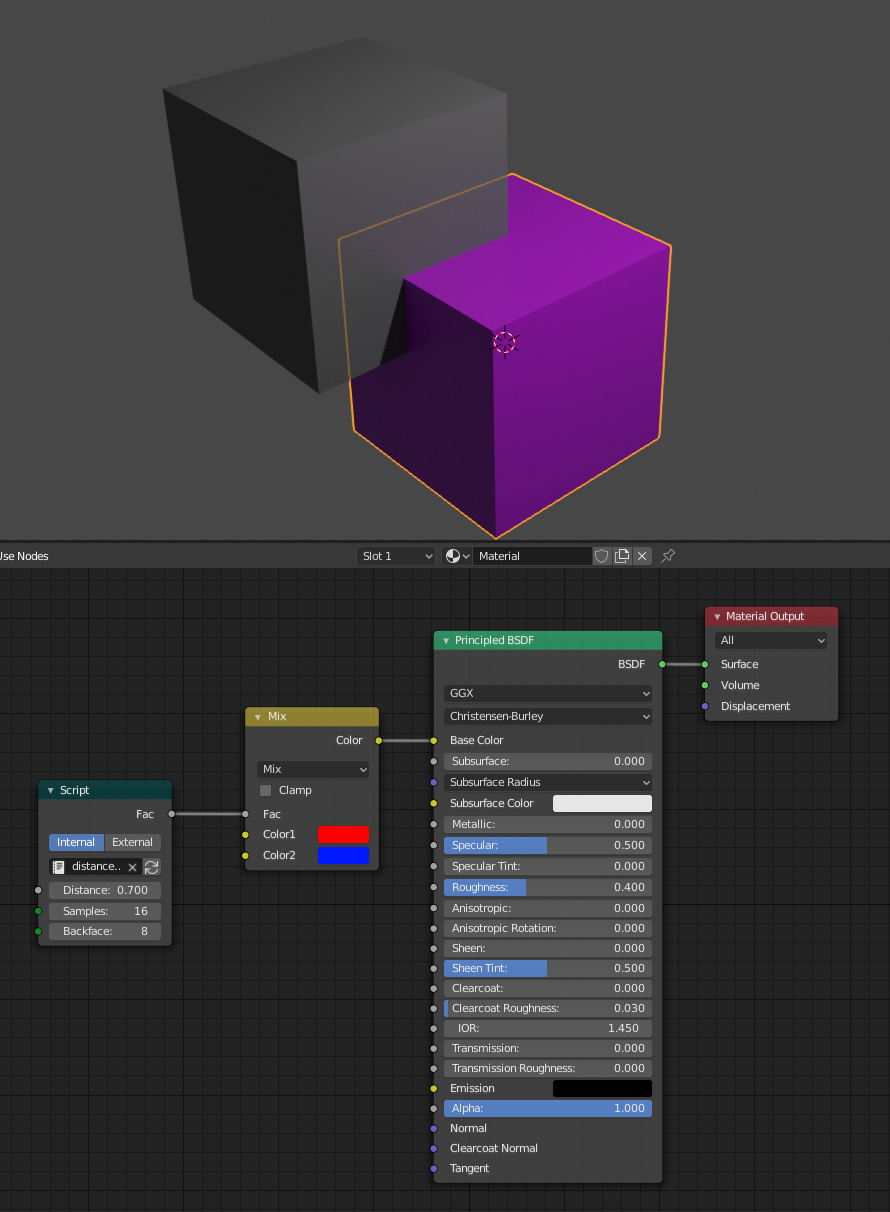
shader Distance(
float Distance = 0.2,
int Samples = 8,
int Backface = 0,
output float Fac = 0 )
{
int i, rng;
float f, randu, randv, ray_t, hits = 0;
vector ray_P, ray_R;
float Dist;
float FDist = Distance;
f = fmod(cellnoise(P*123456.0), 1.0);
rng_seed(rng, int(f * 2147483647));
for(i = 0; i < Samples; i++) {
randu = rng_uniform(rng);
randv = rng_uniform(rng);
ray_P = P;
ray_R = sample_cos_hemisphere(N, randu, randv);
ray_t = Distance;
if (Backface > 0){ ray_R = -ray_R;}
if(trace(ray_P, ray_R, "maxdist", ray_t)){
getmessage ("trace", "hitdist" , Dist );
}else {
Dist = Distance;
}
FDist = min(FDist, Dist);
}
Fac = FDist/Distance;
}