Well, there is something in 3d that is known as triplanar mapping. One of the advantages that it offers over the basic box/cube mapping is that you can blend the edges of the projection in a way that makes the projection seamless.
In others 3d packages/ render engines that I have used, it works like a charm, but to my disappointment, the way triplanar mapping works in blender doesn’t respect normal maps. This is a crucial workflow for shading a scene which has thousands of hard surface objects, it speeds so much the process.
What I want to know is if there is a way to make the box mapping work properly. Is there any custom shader setup that I would do the work? Maybe an addon?
Does anyone can explain to me why blender struggle with it while other major packages does it without problem?
You should read this thread which deals with the same issue.
In short, sometime it gives the impression that it’s working, but normal maps are supposed to work with UVs, I’m ready to bet that’s the same for other render engines, but I’m just speculating here…
The simplest way to fix it is to use bump instead, in cycles/eevee it gives results pretty similar to normal maps, especially if you aren’t in a situation where you bake highpoly to lowpoly (in that case you have UVs ), and are just looking to add bump to a surface.
Just render to a 16bit depth if you are having issue with 8bits (stepping artifacts)
I have an old custom Triplanar (sixplanar ) shader setup that someone shared with me years ago, that does correct the normals, it’s overcomplicated and you have to manually plug 6 images, but it works
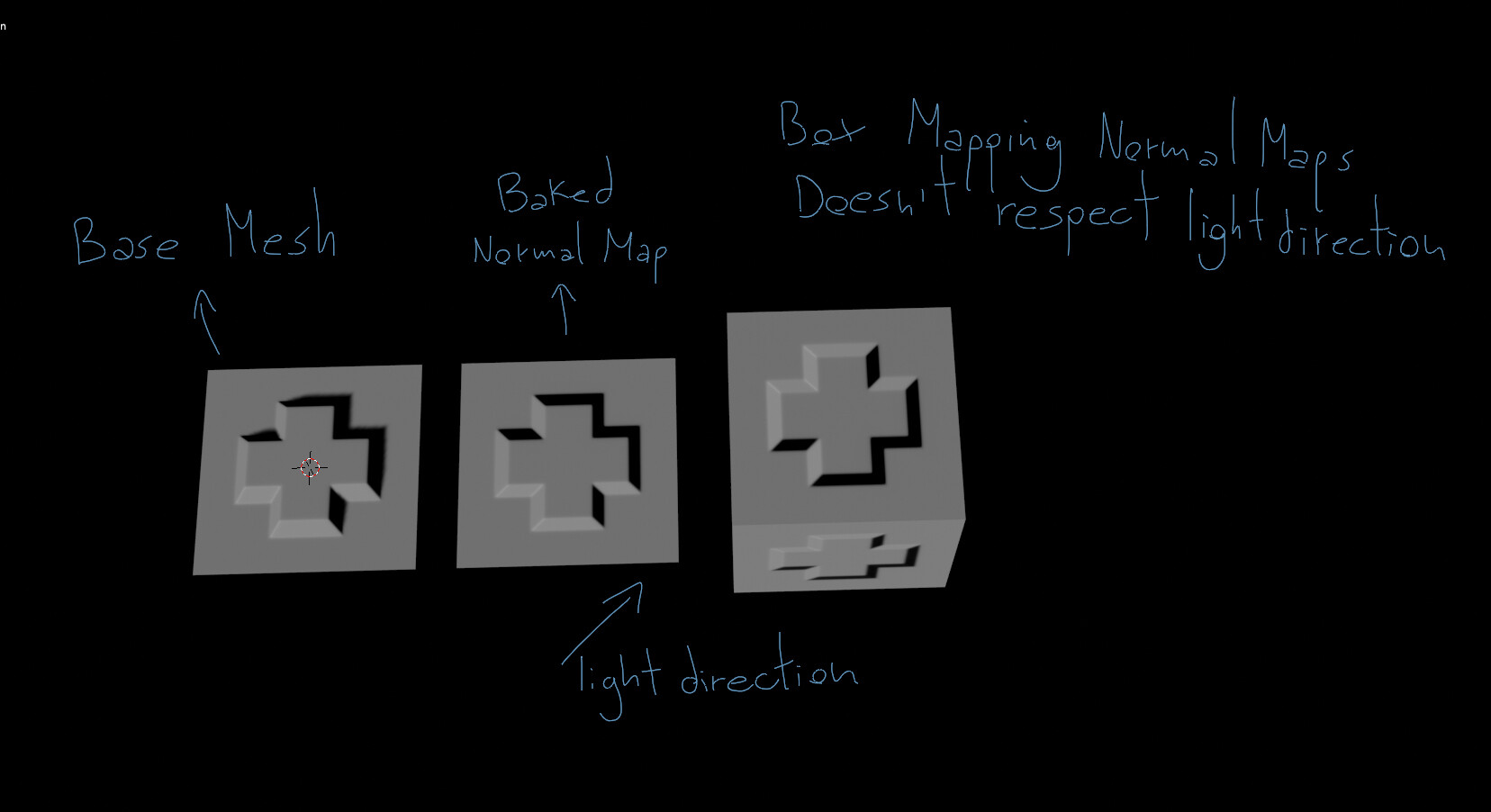
Actually I have tested it in Corona, Vray and Arnold and they work properly. I believe it’s the rotation of box mapping in blender that isn’t compatible with normal maps, but I tried rotating it in the shader editor without success.
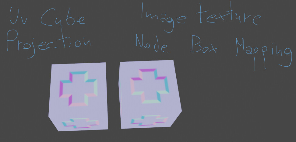
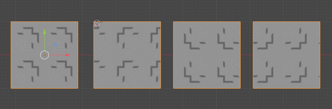
The cube on the left has the normal map rotated the right way, but the box mapping of the image texture node has it different. I believe that is this rotation that is messing with the normal maps.
I will do some tests tomorrow at work with these other engines and if it’s the case that is the rotation of the maps that are wrong I will try to reach the developers.
Anyway, I will try the bump map solution and posts the results here, but from my experience Normal maps and Bumps maps will never achieve 100% the same results (I it was the caso we would not have both of them being used, probabilly the industry would use only bump maps since it is easier to be painted and it’s only one channel, thus less expensive to store).
Awesome ! And I’m sorry if my lack of knowledge was leading to wrong information …
Thanks a lot for testing in other engines, It’s an interesting issue that regularly people stumble upon.
When I look at the image, the side is ok but the top is wrong, maybe it’s possible to swap or invert channels based on how they are oriented… Seems hacky anyway…
Awesome, it would be very interesting to give it a closer look. I think depending on the engine you can get different results with bump maps. And maybe they are a bit more expensive to compute.
In that matter Normal Maps are more predictable and maybe that’s why they are used so much.
The first use of normal maps was converting high poly details to low poly mesh for real time rendering. And in that case using normal maps makes a lot of sense.
At that time bump in some renderers (like blender internal) was giving poor results in comparison.
But now I found that bump maps gave really good results in blender, in fact if you look at the vector output from bump or normal node they look very similar. But I didn’t investigate much closer …
As sozap sayed.In some engines eg directx vs opengl, the channels are inverted.
but i wonder why its the x channel,usally its only the Y channel which is inverted.
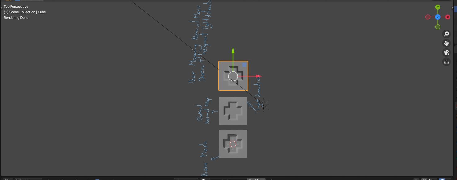
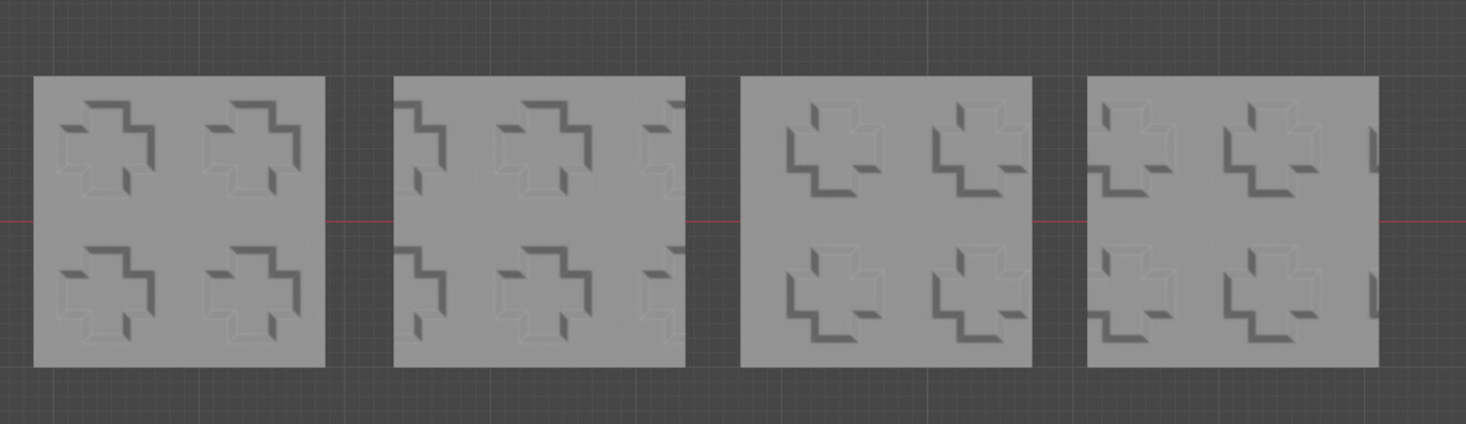
…wait,i have rechecked your blend file,because its not the Y channel.So i pressed 7 on the numpad for a top view and activated the transform gismo to check the directions.
Then i selected all objects and rotated them at the 3d cursor as pivot point,and applyed all transformations.(Ctrl a)
Guess what,you dont even need a invert node.
Well done Pixelgrip !
It’s bugging me a bit and I can’t really understand what’s going on, maybe because it’s 1am here
Do you think there is a connection between vertex order and the way the box mapping is calculated ?
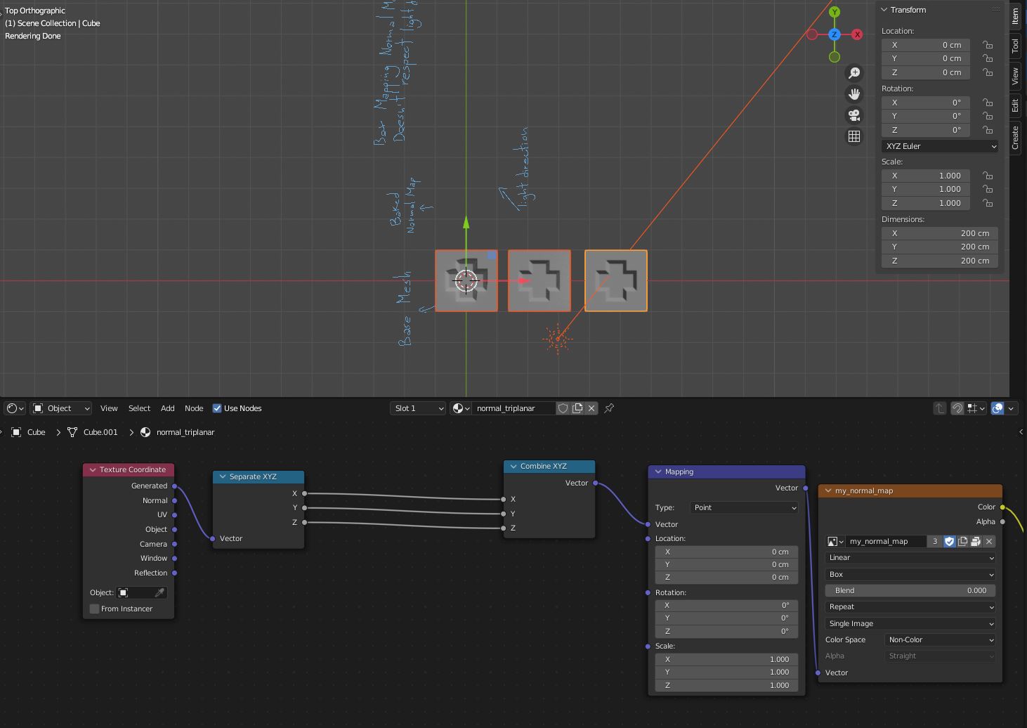
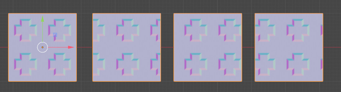
I switched to object coordinates, I duplicated the cube in edit mode and rotated 90° each time :
I guess, the issue lies in how tangent and bi-tangent vector are calculated , and maybe it’s done according to vertex order per face. But my math knowledge stops here, it’s just an intuition…
I get the feeling that it will probably fail badly with some other mesh, hard to get a predictable result…