OK so I have this issue with a custom procedural wood texture I am creating, based on Bartek Skorupa’s wood shader on CGCookie and briefly explained in his texture coordinates talk at the blender conference: https://www.youtube.com/watch?v=kAUmLcXhUj0
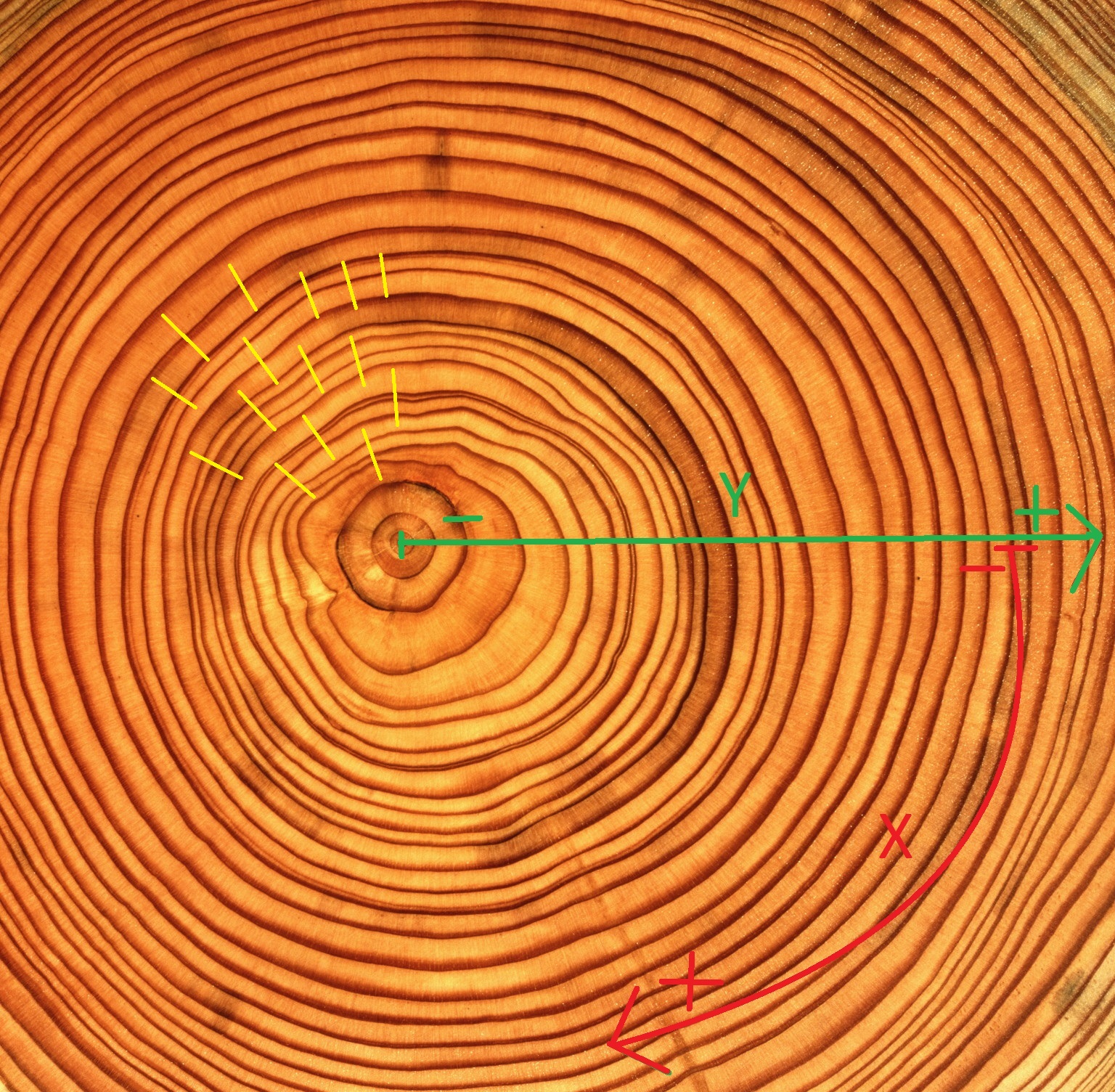
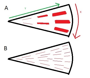
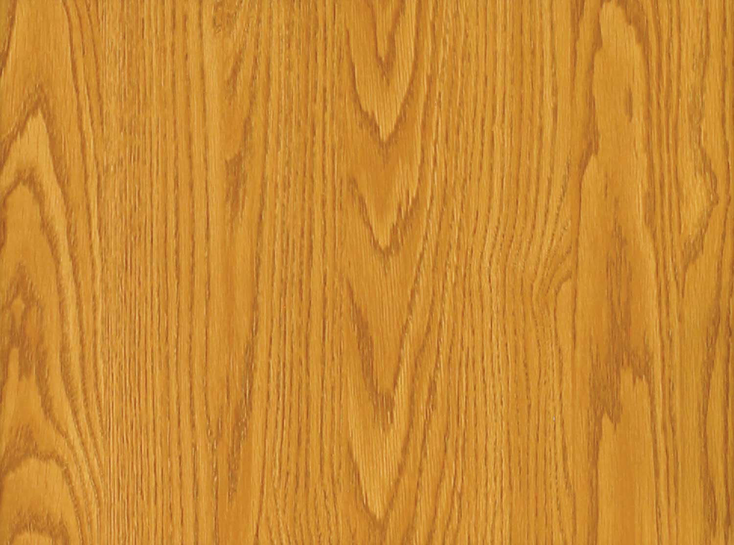
Basically, the idea is to procedurally create a log, from which cross sections would give you a believable wooden plank texture. Now one thing you notice with logs is that features such a wood grain are more easily described by a polar coordinate system rather than Cartesian. I’ve drawn yellow lines on the reference image below that explains the disposition of the grain, as well as drawn where the X and Y axis on such a system would lie (Z is not shown given the top perspective, but remains unaltered from the Cartesian Z axis).
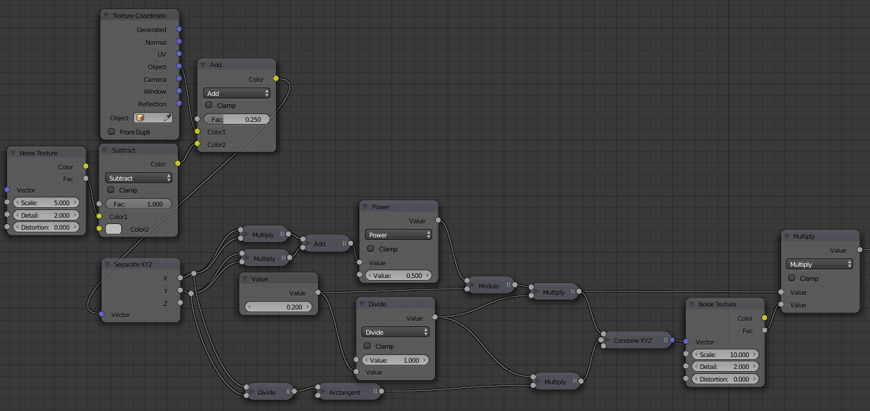
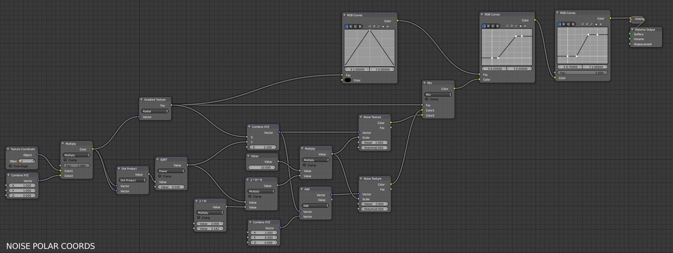
I have created a node group that allows me to map a noise texture in such a way. However, two issues arise from this new coordinate system:
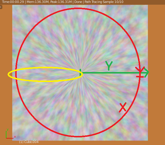
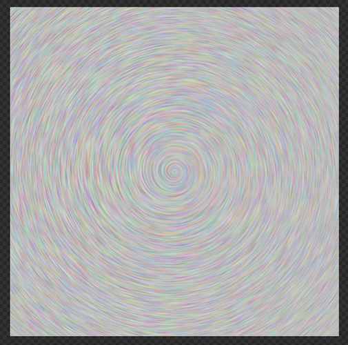
Given the nature of the coordinate system, the further a noise cell is mapped on positive Y, the wider it will be on the X axis (see result below). Is there any way for the scale on X to decrease proportionally to the Y axis without resulting in a spiral pattern (or is this mathematically impossible? I’m learning a great deal of math with this, but haven’t done any for the past 10 years!)
The expected discontinuity at 2π resulting from the fact that the X axis closes on itself (circled in yellow). Now this is expected behaviour, but would there be a way to make it smoothly blend?
I’ve attached a clean blend file with only the part of the shader relevant to this issue so you may take a look. Any inputs on this would be greatly appreciated.
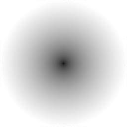
The distance to the center of your log can be calculated with sqrt(x²+y²) (basic hypotenuse), where x=point§.x - center.x and y=point§.y - center.y.
This gives you a circular gradient starting from 0 at the center and going bigger and bigger as you get further away. sqrt(x²+y²)
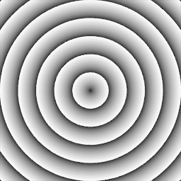
We can now slice this distance into a repeated pattern to create the rings… functions like mod() or sin() can be usefull because they repeat the output when the input grows.
For example sin(x) = sin(x+2pi) = sin(x+4pi)=(…), and mod(x, a)=mod(x+a, a)=mod(x+2a, a)=(…)
With this we get to this: mod(sqrt(x²+y²), a) where a is the distance from one ring to the next.
(because the module function only returns values in the interval [0, a], we must level things up and multiply the result with 1/a to get an interval of [0,1]) mod(sqrt(x²+y²), 0.2) * 5
Now for a bit of caos…
We can create a distortion in the input coordinates, and also a variation of a. mod(sqrt(x²+y²), noise) * 1/noise
To fine tune things a bit, let us limit the sizes of our noise to something like z=a+(noise-0.5)*scale, where a is the mean distance between rings and scale is the size of the variation.
This is with a variation in the modulo…
[ATTACH=CONFIG]428824[/ATTACH]
Because we want this variation to also affect the grainy texture, it’s better to place the noise in the original coordinates, so that we can have some consistency. (see the node setup bellow)
For the radial grainy texture, we can use the atan(x/y) and our rings to create a new coordinate system for another noise, with the atan for the x coord and the ring itself for the y coord.
I’m sorry if I have not been clear enough. The pattern with the rings and modulo is already done and is not what is causing me problems. What is causing me issues is the pattern for the wood grain (a feature that is marked in yellow in my first picture), which is mapped radially. The result from your node group does not address those issues, that is (1) the further the noise (or any procedural texture I can think of which is mapped on a polar coordinate system) is from the center of the pole, the wider it is on the radial X axis, and (2) there is a discontinuity at 2π (not visible on your picture as it is too low res, but it is still there if I re-create your node set-up). Basically you now have the same texture that I already have, with the same issues, only your noise is distorted.
What I mean by wood grain is the small lines all over the rings you can see in the first picture. If you look at it, the further these lines are from the center of the trunk, they will not get wider: there will simply be more of them. I need to be able to do this with my noise: if it is located in a ring which is further from the center, it will be scaled DOWN, so the density is uniform across the trunk, while remaining stretched on radial Y. You can look at the picture below: what I need is B, not A.
I’m showing how to address discontinuity using maths that reflects triangle and sawtooth shapes used for driving and blending. If doing a single flip at 180° you’d get seamless but obvious mirror, that’s why you add another triangle variable based on another input. Where this do a full repeat and obvious seam, the blending of the two makes sure only the first is shown. It would apply to your x input. Unfortunately I can’t make it work over two variables, and it will only work nicely enough for noise, not so great for voronoi.
I did find a “radial checker pattern” whose repeat number increase for each “ring”, which may provide info. Search for hexagonal tiles, wasn’t able to find it right now. Unfortunately won’t be able to try to address this specific case, probably in a long while.
I think that I have kind of solved the issues from the first post, although I’m not 100% happy.
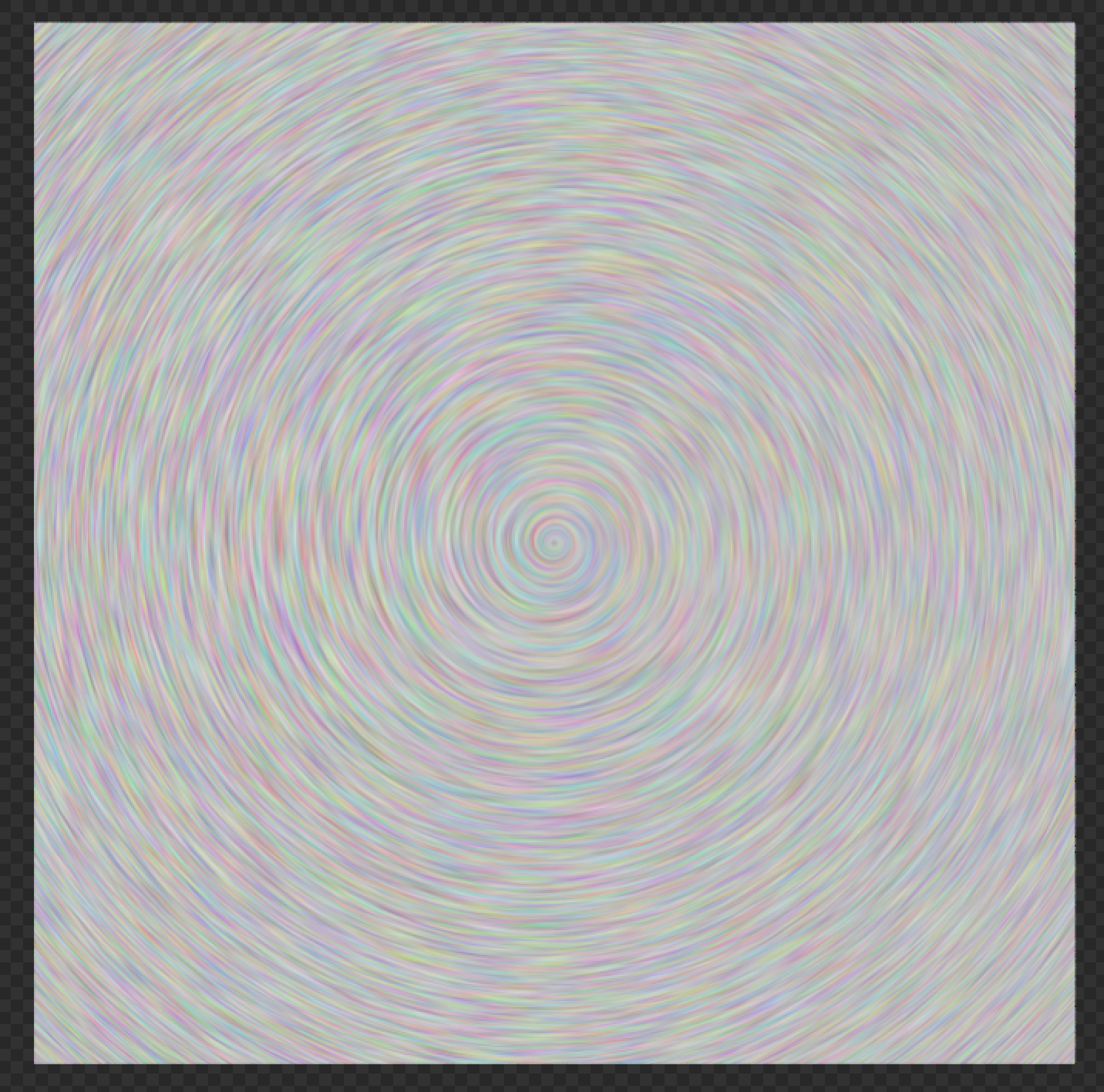
At first let me show you the noise applied using polar coordinates. I will not yet show you the solution, as I have to make some order in it.
Anyway - here is the noise that doesn’t stretch the further we go from the middle and we also don’t have the seam.
Is this the result you are after?
The texture I showed in the previous post has issues. It definitely “spirals”, although I made some adjustments to make it less obvious.
Seam got covered, but it’s done by mixing 2 noise textures, so the contrast decreases in some areas. Some adjustments were needed as well.
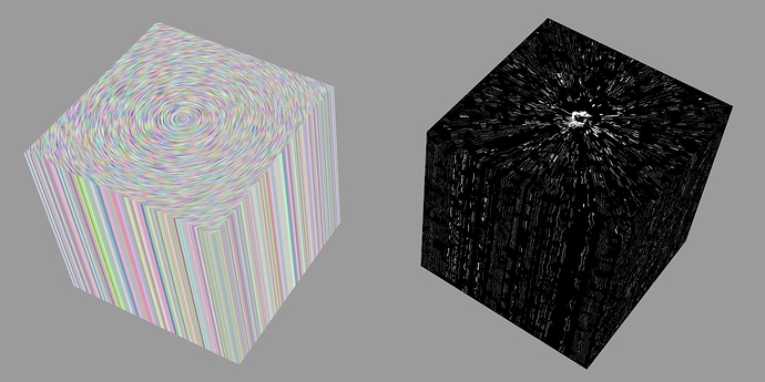
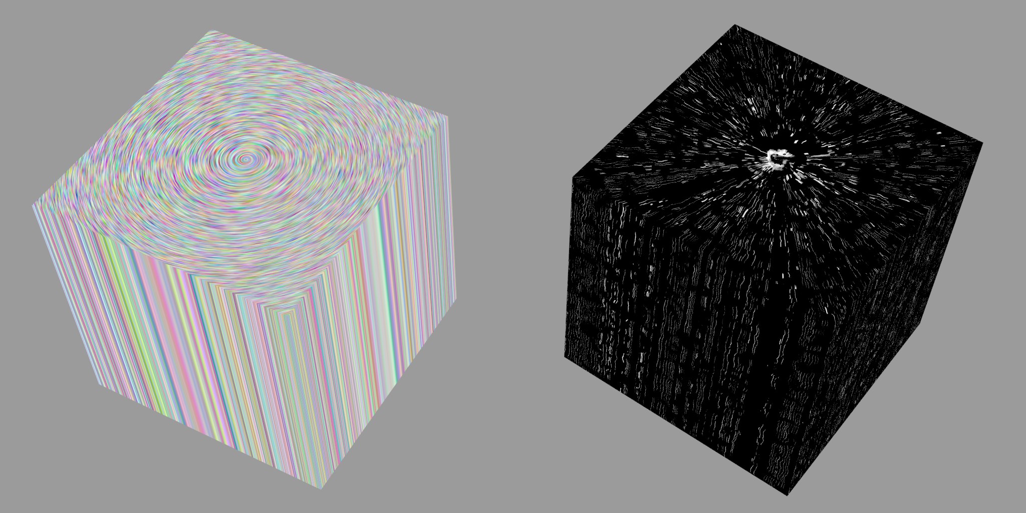
I played a bit more with this and tried to create the wood grain “small lines”. I managed to achieve the result that you can see on the right cube. Unfortunately the shader is a monster.
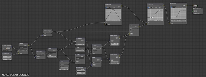
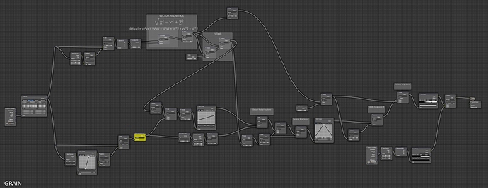
Below the render you’ll find the shaders: First one is used on the left cube and the second on the right one.
Explaining what I did would take me ages. In fact many solutions that I used here are just the result of trials and errors.
Generally several noise textures that drive other noise textures, that drive other… and so on. Complete mess.
I also attach the blend file so that you can analyze those monsters.
Sorry for the late reply, I have been busy with other obligations lately. The effect is not exactly what I was looking for, but certainly the closest thing to it. However, I’m having a really hard time making sense out of it. I’m starting to think that a major issue in all this is the fact that I’m pretty much a beginner and I’m definitely trying to achieve too much with too little experience. I must let go of perfectionism and stick to a more basic wood shader for now, otherwise I’ll just get discouraged. I spent way too many hours on this already. Nonetheless, everyone’s inputs on this have been extremely valuable to me and probably others users. If I ever get to incorporate said effect into my procedural wood shader, I’ll make sure to post it here!
Why exactly are you so concerned about this? For most things that are cut from wood, the radial noise that you are asking about would barely be noticeable. What is noticeable is the vertical fibers in the Z direction. The effect that you are trying to achieve usually just looks like specs. Even in tree trunks, the cracks and cut marks are usually more noticeable than what you are trying to do.
If you are just trying to do it for the sake of a challenge, great. If you are truly concerned about the affect of the noise, I think you can make @Eranekao’s method work. Since the board will only come from a section, you can just increase the density of the noise for boards that you cut further from the center.
I’m not sure who you’re addressing. It seems to be me, based on the fact that I am the one who asked the question, but then again you refer to “Eranekao’s method” in the third person, Eranekao being me.
If the question is directed to me, the answer is this: I don’t believe I was “so concerned about this”, I justwanted to make a wood material that is practically universal and which requires the least tweaking possible. Basically I started from Bartek’s tutorial on CGCookie, in which the great idea is to procedurally recreate a trunk with 3D textures, and from there see how I could perfect it for my personal needs. It is not for a particular project, but just for the sake of learning more out of cycles and shading in general, and since I like to be practical, I would of course use it in future project. Along the way I simply realized that I have a lot of catching up to do, especially in maths
@AustinCPrescot : Also, you say “For most things that are cut from wood, the radial noise that you are asking about would barely be noticeable. What is noticeable is the vertical fibers in the Z direction.”
The radial noise IS the vertical fibers in the Z direction : they are exactly what I was trying to achieve. When you look at the screenshot, the radial noise is seen from top of what would be a tree trunk. That noise is indeed stretched on Z.