Looking for some tips from the physics pros on here

This is a topic I have seen multiple times but I thought I would revisit, given that most of what I have found are old questions and I’m sure have since been forgotten.

Long story short, in cycles, clear coat doesnt look right. Can someone explain to me, with some degree of explanation as to the physics being used by blender specifically, how blender principled is handling clear coat and if you already know any special workarounds mathematically to resolving a few issues like how there is no change to the underlying layer value wise when clear coat is set to one, and why the reflections generally look like they are missing?

Let me add to that. To start. I have been using various different engines for close to 12 years now and I am certainly not new to blender or cycles, and I know what I a asking is not a ““typical”” feature of most render engines, at least that I have noticed. In my experience this almost always needs to be faked. But, given that few engines like cycles and arnold give you an extreme amount of control using math nodes and different mix drivers (well call them drivers because I am actually not sure if there is a technical word for it, if there is I would love to know), I figure, if there is a more accurate way to fake these issues than just eyeballing a layer weight facing value and eyeballing a color value change, then it would be possible in one of these engines, and given the size of the blender community I figure ill start there.

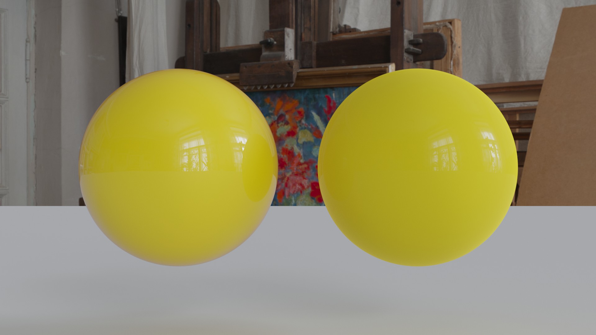
Here is a test comparing a physically modeled clear coat and a shader using “clearcoat” set to 1.

On the left you see the clearcoat in the principled BSDF shader barely reflecting much of anything and generally just feels very flat and dead. On the right, and I cannot speak to the real world accuracy of how physically modeling a clear coat shows up in a render, but it looks much closer to a real clear coat in my opinion. Reflections straight on are much stronger but still does not ignore the fresnel effect, the shadows are darker and much more rich in color. And more than just adding a layer weight node, the rich dark shadows are showing up only where there is actually light fall off, not just because its not directly facing the camera.

CC_Comparison

Like I said, I would really appreciate it if someone who understands the real world math and how blender is handling this can explain to me a little bit how, well, blender is handling this, and if there is a way to simulate this with less guess work, all of that. I am a big fan of using nodes to sorta hack the system a bit so I am eager to understand this a bit better.

In short,the clearcoat layer in the principled shader is added.Adding breaks the energy conservation.The reason for this is,the devs saying that a thin clear coat should not darken the material underneath.if i am not wrong then disney uses a similar clear coat method in they principled shader for this reason.

If you want the darken effect ,then you could mix a seperate glossy shader with a fresnel node into the mix fac.

Keep in mind,that the specular in the principled shader gives you allready a fresnel reflection.

1 Like

I tried that as well and It certainly darkened it over all just slightly and really helped with the reflections but even still it was lacking a lot of the depth. I modeled the clear coat above that you see on the right to scale, offsetting it about 0.2mm from the inner ball. I have sprayed a single layer of clear coat onto an object before in real life and immediately noticed this effect and a single layer is barely 0.025mm thick coming out of a spray can (thinner from a proper spray gun but I notice the same effect) so I am not sure what the logic is that it doesn’t change the color. I know this is for renderman compatibility but I really hope some more accurate option is offered up in the future.

By the way, really glad you replied. I actually was reading your comments on another post about this and found your replies very useful.

All of that said, as far as I am aware, fresnel blending handles what is facing the camera, because logically thats how it works. If you use it to mix then it is basing its fall off from the center out weighted strongest at the edges. From what I have observed in reference and even the render I did above, the darkening doesnt work center out from the camera but rather more like a shadow, where it, yes has some around the upper edges, but is most predominant around the base and sides which are furthest from the large soft box at the top. Is there any way (and I dont think there is but ill ask anyway) to calculate right in the engine render, without using passes and adding the effect in post, to base the factor mix on the light source instead of the camera? and, am I totally wrong about how that works, because if I am, then I am actually very interested in knowing how it does work, and if it is center weighted, then why the effect seems so incredibly different.

The Fresnel in shaders are useing the Dot product of the Normal of the Object and the Viewing angle (Camera).(The normal form your POV).The shaders are closures,that means you have no access to the light source.The shader representing its material properties,If the light hits the Object/material then its reflection ect gets calculated based on the shader properties.

Ok that makes sense. So basically what it comes down to is, Eyeball it and pray real hard that it looks close enough or use render passes and then in post, eyeball it and pray it looks slightly better than close enough, haha.

As sayed,the clear coat layer (in the principled shader) is added,this adds additional light to the shader on top,and makes its brighter.

The more correct Fresnel glossy/material mix gives you a mix output inside a fac of 1. This way the energy conservation is correct.The higher the Fresnel reflection fac is, the less the material is mixed in.Thats why the material is a bit darker.

ahhhhhh ok. Im gonna have to tinker with that more tomorrow. I appreciate it. I look forward to messing with it more. I have an obsession with doing things physically correct… my instructors in college really hated me for not just using the built in settings. “Don’t reinvent the wheel” was a regular part of their vocabulary with me. I’m like, sure, when youre a paying client giving me a deadline but right now im in class getting learned :joy: I wanna mess with stuff and find out how impractical it is later and then have the tool when I need it. Not like its costing me anything extra financially… already paid for Maya lol

Here is a good PBR guide

I really appreciate that. To be honest most of this is all stuff I know very well but I saw a few bits in there explaining how PBR is simulating real world effects that I really like. That’s really where my understanding is not yet where I want it. For the most part, I have a slightly above average understanding of physics in real world depending on the focus, a pretty high level of understanding of shading, and an excellent understanding of when something doesn’t look right but I don’t always know enough about how the engines are solving for real world math to know how to fix certain issues all the time. Translating real world physics to how cycles is simulating that information is the next big hurtle. I really appreciate the documentation though. I think that’s the first thing outside of a forum conversation In a long time to teach me something that i wasn’t specifically digging for. I say specifically digging for because I’m learning all the time but these days it’s usually through the process of troubleshooting and the research that comes with it.

The principled clearcoat as mentioned is simply added. It breaks energy conservation. It has a flawed roughness implementation - it looks better but you need to be careful what you put into it. And it doesn’t affect the base layer at all, specular is unaffected and there is no absorption or other energy loss going on (i.e. layer inter reflection).
If you want a topcoat that simulates depth you need to setup your own node group to do so. Luxcore has absorption built in if you want to look at a reference. My own isn’t physically based, but has separate controls for angle and thickness (and total), but not based on a thickness measurement.
If you want absorption, I suggest using one principled without topcoat but reduced specular that is reduced in effect based on angle/thickness of the topcoat, and a separate black non specular principled for topcoat only that is fresnel mixed in. For topcoat roughness, make sure it’s input can’t go below 0.0178 - that will always give it some roughness but it won’t break if using maps going below this buggy threshold.

Using PBR makes it physically plausible to a greater extent than before, but still far from physically accurate. Internally, the shader is still dividing into different terms and adding them together. Simulating physical behavior is far outside of most renderers. Maybe this is something for Mitsuba, but certainly not for Cycles and most other renderers that still uses tricks to get to a result.

Thank you so much. Yeah I have sorta noticed cycles has been cutting more corners for speed and compatibility. Nothing specifically against it. The results are amazing. I have used every engine under the sun (exaggerating, but quite a few) and cycles still looks just as good as 95% of the rest of the lot so its not a complaint yet. I know more on/off switches to keep everything physically based for those who want it are on the to do list. I certainly hope they come sooner than later just for my own personal taste but Im also no longer tied down to just blender like I was back in 2014. Even still, I like that blenders nodes are so robust that I can kinda Frankenstein the results I want together when I don’t want to re-shade a scene in another engine.

Well of course its never going to be 100% physically accurate. I use the term “simulate” loosely. If it were all always as simple as, oh, theres a shader for that, then the uncanny valley, strictly in terms of material development, would already be dead and buried.

It’s not cutting corners wrt topcoat. It’s exactly what the disney specification at the time was. I’m not sure if disney has the roughness bug though.

Just my personal look on it is, its not that a corner was cut because anyone didn’t want to do the work, but like you said, because thats what disneys specifications were. I just have never been super in love with working in renderman to begin with. I certainly can but its just personal taste. I know the purpose of it and it works beyond wonders for what it was built for, but I also feel like you have to ask whats important to you personally in an engine when you are deciding which one to use and I have always leaned to the side of Arnold, IRay, Octane, Luxcore, Keyshot, and less to the side of Renderman and VRay. Not bashing them at all. Just not what I am looking for in an engine for a lot of my personal projects. Im just saying I feel like the target audience of the engine is shifting and thats not at all a bad thing for blender or the developers or 99% of people using cycles. I just don’t really care for the model that much personally so I look forward to some of the features I have seen in the to do lists that allow people who use my preferred work flow to still be able to use it and not have to pick one way or the other. I think once those features are in place cycles will be even more of a titan also just because you have the choice where even the engines I really love dont always give me that.

I just rebuilt the shader. I will post it here soon for thoughts. I swapped out the principled clear coat because I though about something, if you mix something that has a fesnel facing value into another shader with a fresnel facing value by using fresnel, the front becomes extremely flat. The front is virtually untouched but in real life that doesnt really happen. That said, I may have misunderstood your method of mixing it in. If I missunderstood your suggestion I would love to know how I can maybe do that differently so I can compare it with what I did now and my reference.

Also, I did quite a bit of research recently on the darkening of an object with a top coat. From what I can see it has little to nothing to do with the thickness (except for how angle influences how much light is bounced at what angle on a curved surface because of its depth which makes more sense after what I say after this) but rather the disparity in IOR of the top coat vs the bottom coat. If you have an object with a higher IOR base coat than top coat then light will travel straighter through the top coat and ultimately see little to no difference between the top and the bottom but if the top coat has an IOR like that of a premium car top coat (I say premium because some top coats are specially engineered to have IOR topping 2.0 for better reflections and richer coler) then the difference between the paint and the top coat becomes very large, causing light to reach the bottom coat at a larger angle causing the specular to appear lighter and less light to bounce directly back to the viewer making it look darker. Really fascinating actually. I also am not 100% sure that that is something thats math will translate directly into a render result that matches the real world but in my test I think I got it pretty close.

I will pack up the node group later and show the test thumbnails and post the material here. If you are inclined to take a look and weigh in with any suggestions I would really appreciate your thoughts. Like I said, I really dont know how accurate the results are in terms of a proper representation of the math so I am interested in getting your take.

So here is how the material turned out. The specific effect of coat thickness is most pronounced on materials with a bump map. The absorption is multiplied by an inversion of the bump map so it gives the concave areas a little more saturation and a little less value. Everything is treated with a very liberal and trial and error based approach to real world principles I researched over the past couple days. The most important one being that the darkening is happening due to the difference in IOR not IOR on its own, so there are a number of math nodes that went into this. Here are the results. I think they came out pretty good but I know the math can be improved on still. I think there is also a point where you have to ask, are the changes youre making so small that they no longer “push it that extra inch” but rather just waste a lot of time rendering when a simpler setup would have done the trick. Even still, just as a proof of concept, I am curious how much further this could be taken.

As a note, the render times on all of these were nearly identical (within a few seconds either way on average) to just using only the principled shader. The down side is I did notice significantly more crashes in branched path-tracing. There werent too many problems in standard path tracing mode, however.

Left side is my shader group, right side is principled with glossy coating. My shader group was setup with a very thin coat to try to simulate the same thickness circumstances.

Just a principled with clear coat. No fancy car paint flakes or anything. This is just for testing purposes.

My go at a clear coat. Still no fancy car paint flakes or anything. This is just for testing purposes.

Some settings thumbnails

And here is a test comparing a thin coat to a thick coat. Because the absorption is “deeper” in the thicker coat, it will appear darker. Additionally, it is being multiplied by the difference in IOR to boos the appearance around the edges that light is being bend away from the viewer darkening the surface based on the difference between the 2 coats. In this particular test, it takes advantage of a node tree I setup which also accounts for bump depth to determine that the coat is thicker in those areas and to amplify the effect more in those places. The IOR and roughness are setup to simulate a thick polyurethane glaze so there is also a smaller difference in IOR meaning it would not be as dark as if I had used a clear coat based on the Mercedes clear coat which from what I have read is specially formulated to be nearly IOR 2.2 for richer color and brighter highlights. I dont know the validity of that statement but from what I have observed in pictures, I could imagine it might be true.

Although very VERY hacky and I dont recomend it, the surface thickness is set to a large value like 100,000 micro meters, this will give the appearance of being suspended in glass 1 decimeter thick. I say I dont recomend it because althoug the material it’s self acts correctly, it will not interact with other light from the scene behind the object to transmit light so it it will begin to look like a grey blob. I toyed around with ideas of how I might be able to incorporate transmission just as a POC but realistically, there is no “good” way to do it that I can think of and honestly, if it’s so thick that you can see more than a grey crown then you should just use a solidify modifier anyway with a clear coat outer, so I tossed that idea about as fast as it took me to come up with it.


I will post a download for the material later if anyone wants to mess around with it. Improve on it, make suggestions, just use it, whatever else.

1 Like

Thanks for your tests.The Node looks good.Not sure about the math behind the thickness and absorption ect(Its hard to see the nodes atm).Otherwise looks great so far.

As example, 10cm Thickness of clearcoat makes not so much sence.Maybe for a resin Material,but for this you would setup a volumetric material anyway.

As sayed,would like to see more your math behind this,maybe with source.I like it,if the math is based on Optical equations.

The statement about 100,000 micrometers was more just to say you could do it and it looks OK so if its a background object it wont take as much render time as doubling the material with a glass material, if total realism is the goal, but I wouldn’t use it for something up close. Like you said, 10cm is really thick. Even for resin I can’t think of an application for that. Much more realistically, most paint clear coats are only 30-220 micro meters thick and thicker applications like polyurethane coating (like I did in the stone test) are around 0.5-4mm thick, so you would set the value to somewhere between 500 and 4000 micrometers. Like I said ill post the material in just a few and you can look at all the math and tinker with it. If you see any ways to improve it I would love to see what you do with it.

As mentioned, the principle is light moving from one medium to another with a lower index of refraction will see a loss in light sent back to the viewer because the light is bent before it reaches the next material diverting some light away from the viewer. That is a little hard to simulate in just a material so like I said also, I took a very liberal and hacky approach based mostly in trial and error to get it to work as intended. It was mostly using the math to get it close to some reference I have here in my office and then just tinkering with different parameters which may or may not be ““correct”” to get it to behave as closely as I can get it to the real thing.

I will post the material in just a couple minutes for you if you want to pop it open and have a look.

Its hard to make a Multilayer material with just a mixshader(Otherwise the Fresnel mix is ok for most of dielectric materials).The reason is,that you want to keep your light going through all layers and reflecting back with the absorption through all layers.