I am an engineer and product designer and I am starting to use Blender as my rendering software.
My designs are basically made of several components so the final product is an assembly of them all.
My workflow is quite straightforward:
modeling and designing in Fusion 360
rendering in Blender
post-processing in Photoshop
The transfer from Fusion 360 to Blender is made through a file conversion. I export each component as an obj files that is then used in Blender. Since Fusion is not able to generate a obj file of an assembly, each, I need to rebuild the assembly once in Blender.
I would like to know what is the best way to position objects with accuracy as I would do in a CAD software. For instance, I need to insert a shaft in a hole and be sure the shaft is well located both in depth and concentricity.
I am asking you guys for some tips to make the most efficient and accurate assembly possible.
The Empty is an auxiliary objects that can be used in many way to drive your geometry parented to the target as snapping point. Blended Manual: Empty
And I remember in past when I used SolidEdge at work many parts we made for assembly inside these, a guide geometry such as cylinder, to have a concentric point to placing bolts or shaft into particular positions.
The .fbx export solution worked but created lots of lines connecting my geometry to the ground…
I will follow my workflow (UV mapping, material applying) and see if everything works nicely with that method.
Any idea for the lines ?
They seems to be impossible to delete…
I have an assembly in Fusion and need to have the same in Blender.
There is no right or wrong solution but I need to have that assembly ready in Blender to be rendered.
Initially, I exported each part as a separate .obj file and recreated the assembly in Blender by adding each component. But that requires an accurate positioning of each parts with each others to have an accurate assembly (can’t work by coordinate or rotations). And I don’t know how to do so in Blender. The idea would be to be able to tell a geometry to snap to a specific location of another geometry
The .fbx solution works, I do have an assembly in Blender straight from Fusion, but for some reasons the fox contains unwanted lines. I also found that my material settings doesn’t work with the fax solution (scales or orientations are messed up).
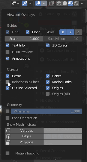
The lines looks like relationship lines, it is only lines that show parts relationship with eachother nothing that will show in render. You can turn them off in the overlay panel.
When you import an hierarchy the scale of the parent can be 0.01 and the rest of the parts in 1 this will result in some scale issues. The solution is to apply scale to the whole assembly or to scale your materials by 100.
I do have the proper scale applied because I am working on the same bender file as my previous project were I use the properly set material. Parts are the same size, same scale but material is not displayed the same way
I have tried another method, just by setting the part origin, then put the cursor at the suitable position and then snapping the origin to the cursor. Works but part is not well orientated sadly…
Question is, how shall I keep the same size while changing the scale.
For instance I have a object that is 10x10x10 mm, scale 10 and the same object that is 10x10x10mm but scale 1
In CAD applications you have different mate constrains and much better snapping so it usually much faster to snap things together in a CAD app. That’s why I suggested to use .fbx files so don’t need to do that in Blender. You can do it in Blender but it will not be as straight forward as in CAD.