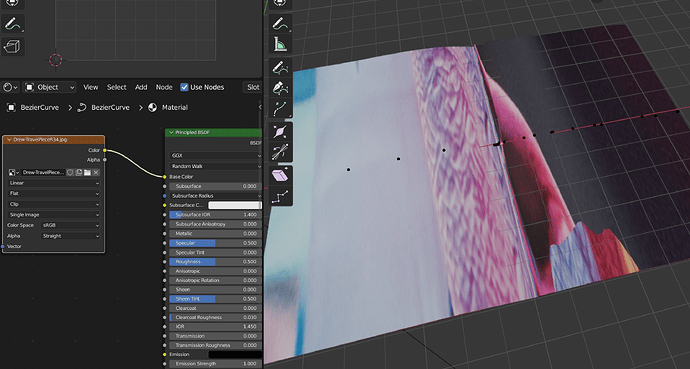
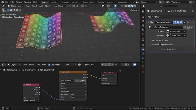
I need to see how an image texture looks on an extruded bezier curve before converting that curve to a mesh. In other words I’m trying to work non-destructivly with beziers as long as possible. I can create a material and image texture and apply that to the extruded curve, but I can’t figure out how to proportionally scale the image texture to fit in the shape of the extruded curve. As you can see in the screenshot, the image texture is huge and bleeds outside of the curve I’ve created. How would I get control over scaling and positioning the material without converting the bezier to a mesh and UV unwrapping it? I’m trying to create open pages in books and brochures, hence the curve that looks like a plane.
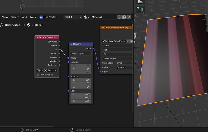
Have you tried a mapping node?
Shift a > Vector > Mapping
EDIT: You can still use the UV map although I don’t know how to manipulate it in the UV editor.
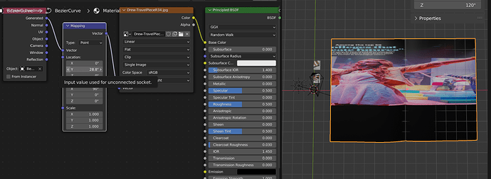
Thanks. I just tried vector mapping, and that’s a possibility, though I can’t get my head around why the image scale looks distorted along the Y axis.
I’m not sure, but why aren’t you using the UV coordinates? Did you apply the scale? Ctrl a > Scale
Honestly because I’m hacking my way through this. But also when I use the UV coordinate, the UV just looks like this, and I can not figure out how to bring it more in line. When I use “generated” coordinates, it just seems to be a bit more predictable, though I still don’t know what’s up with the random distortion.
I’m applying this to an extruded bezier curve, so technically there is no scaling to apply yet. Though I did try that and it didn’t have an effect. Thanks for your help though. Truly appreciated. LMK if anythign else occurs to you.
I will do that.
Rotation must be zero.
If you want to rotate, rotate the source image
If you are converting to a mesh anyhow - then just make a copy and convert it to mesh.
Have you considered making a nicely subdivided plane and shrink wrapping that onto a precurved mesh? So you give a high quality mesh / UV the shape of the opened pages.
Or add a well subdivided plane, turn on proportional editing with the falloff set to sharp and pull down the center (fold) edge on the Z axis. You will need to then select the two outer left and right edges and pull them up or down as well.
If you do this to several different shape keys you have a single ‘template’ with multiple variations built in. Add curled corners etc as extra shapekeys…
Yes indeed curvy planes from curves (bottom) to have nasty UV… but after converting to mesh a simple unwrap follow active quads and maybe a horizontal scale (above)… and the simplest texture map…
OK. Thanks for that okidoki. That’s illuminating for sure. This will probably seem ludicrous to others, but I need to see how a a very specific sized image on the model looks so I can extrude the bezier to match the aspect ratio of that image. That’s my ultimate goal and current challenge. Once the extruded bezier is of the right proportion to the image I can convert it to mesh and unwrap (no problems with that part of process). I have upwards of 30 of these things to do, and they include all types of formats/aspectio ratios, different number of pages/panels (some are brochures), and in different states of being open.
If only there was a way to place the image on the model in a manner where blender doesn’t try and fill the whole model with the image (which is where the stretching seems to happen) Maybe shrinkwrap approach like Matakani suggested. I’l try that next.
If you have to repeat a specific process 30 times, that seems like a good candidate for writing a script that can iterate for you ![]()
Why not just shorten the mesh (in my example Y axis) according to your image… fitting the aspect ratio… ??
Okidoki. Only because once I convert to a mesh I can no longer tweak the curve. With that said if there is no way to map an image texture to geometry without the application stretching that image to fill geometry then then I’ll accept that as a limitation and move forward. All good.
Much appreciative of all the suggestions.
that seems like a good candidate for writing a script that can iterate for you
It sure does. I wish I had those skills. Maybe some day…I’m still new to Blender, but I am all about automation in my profession as a graphic designer.
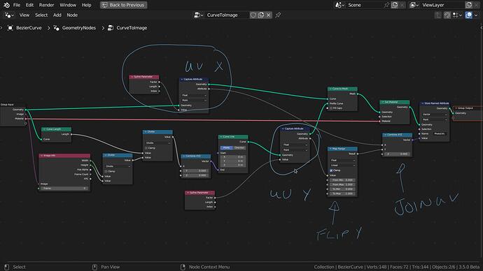
This seems to work with GN nodes. At least with a flat curve (2D - flat on one axis)
…
EDIT
I have corrected the file in my answer below.
This is great DNorman. I get conceptually what you are doing with the GN, but I’m really brand new to Blender, and right from the jump I’m having problems recreating this solution. For example I don’t have the same options you do after creating the GN modifier. So you’ve got the option to apply an Image and Material, and I just have the default inputs.
You’ve added an Image Info node, but I don’t get that option when I search for it. Clearly I’m missing something very basic. I will download your file and study that, so thanks for sharing the knowledge.
Sorry I will write all that again as the instructions were not good.
I will be back.
Arrrrg It was working yesterday! I will have to recheck the setup, something is buggy.
No worries. And thank you. I am interested in this, and am digging into to some tutorials this evening, but please don’t sweat it too much.
Some thing is wrong with the math, I just don’t understand why it worked for the 2 images I used, I will investigate. I am sure it is possible. ![]()
Be carefull Geometry nodes are addictive!
I have changed the math, and the UV mapping in the GN setup.
The UV’s now use a named attribute so there is no need for the UV output in the Geometry node.
Here is a new file:
2.blend (508.1 KB)
I am pretty sure the dimensions of the images should be correct but there is still a slight inconsistent stretching in some parts that has to do with the curve handles length (the length between the 2 handles of the curve vertices.) I have compensated by scaling one of the handles where I noticed the stretch.
The new UV method does map the whole image for non square images (the old file did not)
That is because I had to “create” those inputs. In Geometry nodes if you drag an input from a node to the grey circle in the group input node it will create an input with that parameter.
You can use the setup I have made by appending the GN node group from my file into yours. Blender will append the material with it but you have to re-select the image in the GN node image input and apply the material to your curve.
To use it on more than one curve both the GN node groups and the Materials need to be single user for each curve.
To change the image you have to change it in the GN node input and the material setup.
It is not perfect (due to the uneven stretching) but is much closer.
