I intend on only applying this method to some models of printed circuit boards im working on. i believe that i would only see 5 to maybe 7 different types of layers at a time. The software i am using to design the boards always exports with the same color pallet, so once this material is configured correctly it should be able to be applied to multiple PCB’s without too much effort (i hope…). though i will look into optimization and hope to use this nice little trick for years to come!
Thanks again Rich,
Blender rocks!
You can always use a separate RGB node for this, this will output three masks based on the different color channels in the image (which you can use for masking). Blender 2.69 will also have a separate HSV node as well for even more possibilities.
I am very interested in this method you speak of! but unfortunately I would not know where to begin. are there any links or terms that you might know of that i could search for?
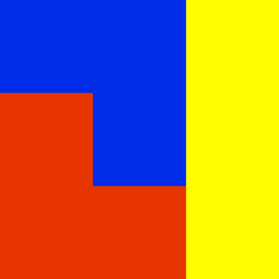
selet the faces for one color then in the material panel
add a new material and assing it to these selected faces
then do the samethng with other faces
unitll you have the qty of material you want!
then in cycles for each material you can add a shader as you want!
Assigning whole different materials will only work in your first example, because each color maps entirely and exactly to specific faces. With your latest pcb texture, imagine if you had to have toplogy that exactly matched the shape of each bit of text and each circuitry line. Assigning multiple materials would be a terrible technique for what you have in mind.
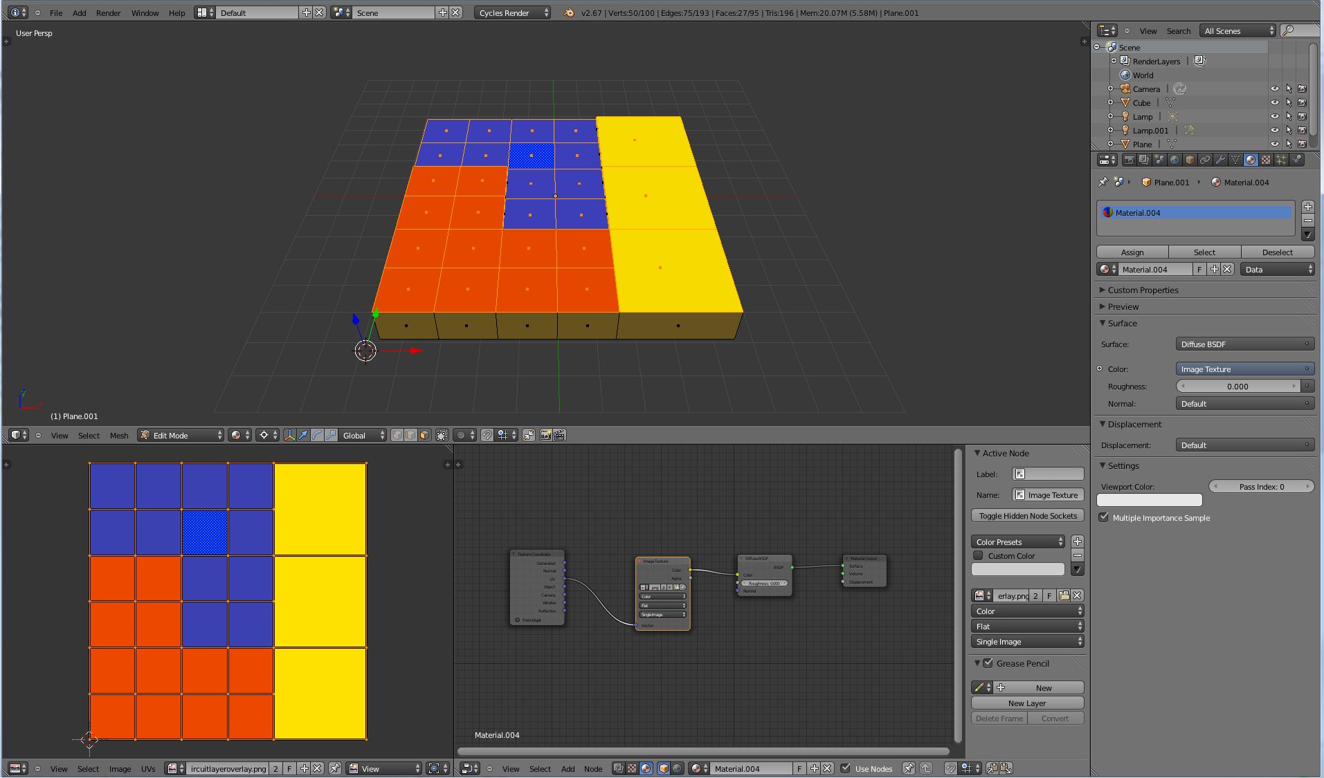
These allows the user to select the exact color using the “dropper tool” and then define a threshold value (~0.1 - 0.01) above that color’s B/W value.
it seems to work as expected for me, but to anyone who does try this Should Be Aware:
The order in which you select your colors is essential! it must always be brightest to darkest!!!
Where there are sets of two values that then are connected to an “Add” node, it consist of the target color and a value of roughly 0.1 (the positive match threshold).
if you find that you have two target colors which are very close to each other in the grey scale spectrum, then consider making positive match threshold smaller/tighter or even try adjusting down one of the target colors which will move the range in a negative direction.
Also note each “Sub Material” that you would like to have must be created and defined in the same nodes that do this whole cascade of comparative “Less Than” statements. i am not sure how to define some material nodes elsewhere and bring them in as maybe a group…?
correct! it was quite easy to apply this method to just about any simple uv mapped mesh so long as you limit how many colors you use to define your shaders as it could be quite cumbersome defining more than 5 color/shader values…
but again, the model i use is for rapid prototyping and the colors never change. so once this is configured it is easily applied and re-applied to new imports.
if you look at the uv map in post #8 you can see it contains four different colors of the various layers on the printed circuit board.
1.silk screen layer
2.solder mask over garolite layer
3.solder mask over copper clad layer
4.bar copper clad layer (also sometimes gold plated)
to achieve the effect of that last render i simply used wave textures fed into the shades normal map.
it was the only way i could see to use this model as the mesh was inconsistent with the uv map and i really wanted to use shaders for this.
however displacement is nearly impossible unless someone knows how to fix that mesh a little so it could be subdivided???