I wonder how could I mask normal maps. I don’t want to combine them, but to apply different normals to different parts of my mesh using a Factor texture. As you can see in this picture, I’ve tried to simply use a Mix node (despite it inputs colours), and, well… As expected, it didn’t work:
Is there a node to convert vector to colour, or another workaround to mix normals? Do you see more problems within my net?
Thanks,
Álex.
EDIT:
Actually, it does work, or at least it seems correct until the material reaches the NormalMap node just after the highlighted node in the picture, when a strange shadowing appears. This is how it looks then:
To experiment with normals, I always use sharp glossy node to easier spot if I agree with what is happening.
Normal map node takes a normal texture, you know, mid blue etc. Do you get mid blues out of the previous nodes going into that? Does it improve if you simply bypass the normal map node?
Without being able to test with a shared project, I’m just guessing here.
I find that the best way to mix and mask normals is with a mixRGB before a normal map node. There are complex situations where breaking out the XYZ vectors like you have and performing some math is necessary, but a simple setup will due if you just want to mask some bumps.
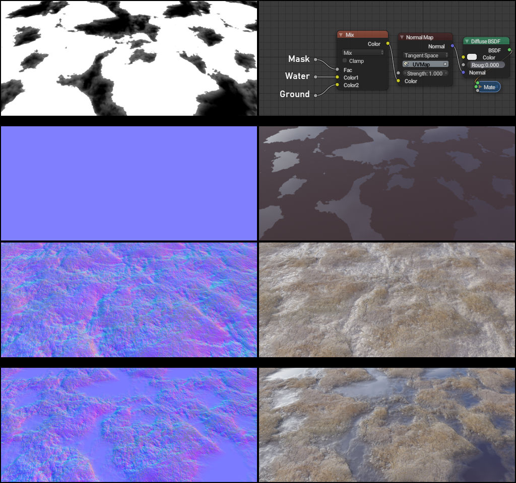
I happen to be working on a smart material of sorts that does just this to add water puddles. Here’s a breakdown:
Oh, thanks! But I already tried something like that. The thing is, I wanted to use the normal map before the MixRGB node in order to set the strength of each bump level individually. I thought that I could use something like a ColourRamp or a Bright/Contrast to mimic that effect on a bump map, but it seemed to work out differently. Do you think we could actually simulate the strength effect by using these nodes? I mean: theoretically I think (and thought) so, but it didn’t look nice.
Yes, and in fact you can see that in the example. Look in the bottom two images. See how the bumpiness gradually falls to flat at the waters edges. That’s controlled by the black and white mask. Expanding on that mask, I can manipulate the normal strength to raise/lower the water level and change the opacity.
What you want to do is set your overall max strength on the normal map node, then control your per-texture strength by mixing them with RGB(0.5 0.5 1.0)
So looking at the nodes in my image above, you’d have two extra mixRGB nodes plugged into Color1 and Color2 of the first mix. Then plug your two normal textures into Color1 of these mix nodes. Set Color2 to (0.5 0.5 1.0)
Now you have a fac slider to control the strength of each normal texture individually.
Looking at your nodegraph there is something wrong :
You can’t plug the output of a bump map node into a normal map node.
But you can mix normal maps as cgCody pointed out, or mix the output of 2 normal maps with the same technique if you want to set different strength values for each normal map.
Same with the bump nodes , if you want to mix a bump node and a normal map node then mix their output with a MixRGB.
But you can plug the Normal output of a Normal map into the Normal input of a Bump node. And Bump node Normal outputs can be plugged into other Bump node Normal inputs for successive effects/building up bump at different scales.
The Normal map node itself however, doesn’t have a Normal input socket, so normal maps will need to get mixed - somehow. But the math of doing that is stupid complex unless you want “some bump effect” and don’t really care about the actual normal angles it produce.
You are definitely right about normal angles. A mixRGB is going to destroy them. I typically only care about that if I want to add a detail map (ie bumps/cracks/etc) onto a surface map (geometric shapes/paneling/etc)
It’s not too complex. There have been some papers that simplify the problem. I have a node group that I use for this kind of thing.
The top row is a straight RGB mix. You can see the normals are dulled out, and incorrect.
The bottom is a more proper way to mix the normals.
cgCody, could you upload a blend file with that node setup please? I think this is exactly what I’m looking for but I don’t know enough about nodes to work out some of the things you’ve done there.