Medieval Castle and Geometry Nodes Workflow

Damn !! That’s great !!
Thanks a lot for sharing your process, it’s quite inspiring !
I was thinking you may find a simple solution for that, but anyway ! that’s really cool ! well done !

Something simpler could be, extruding the curves, then extrude each faces to make a “poked face” by scaling at 0 the extrusion, that should give a similar pattern, after that you need to get rid of unwanted geo to keep only the diagonals. That should be easy because it’s part of the extrude selection. Not sure it will work in practice, but your solution is quite clever !

I’ve got another question for you :
Right now I’m having issues to align the curve tilt according to another mesh normals :


It’s the red parts in the capture, they are based on some curves.
I use a dot product on the mesh normal (that is a cubic shape not seen in the capture) and the curve normal and plug that into a arcosine to get the angle.
As you see, it can work but it’s failing at some angles, and if I start to distort the curves it turns into a big mess.
Have you find a solution to deals with situation like that ?

That is genius, well done figuring out that solution! I’m definitely bookmarking that!

1 Like

Oh man I was sure I would end up finding something better. Thanks for the pointers !

At first I was wondering how to poke the faces like you suggested but I remembered something I read on BSE. Extrude faces and scale the top face to 0 to get poked faces.

So to reiterate :

  1. Resample curves
  2. Curve to mesh, but you can’t just use the direction inside the Curve Line node because it will be extruded along the local normal (or tangent ? didn’t check)

(Edit : the Curve line direction should be (0, -1, 0) but the problem doesn’t change)

So my solution was to instance a curve with 2 duplicated control points, then offset every other point using a modulo with the index.

  1. Poke the mesh using an Extrude and Scale Elements with 0 scale

Tha was a piece of cake ! Note I used a slight offset in the Extrude because I use the edge angles to filter out the edges that are not diagonals later.

  1. Now we need to heat up the brain cells a bit to filter in only the diagonal edges. The selection is threefold.

First we remove the “horizontal” edges by checking the unsinged edge angle (honestly that was a shot in the dark, I can’t really explain why it works)

Then we get rid of the vertical lines by checking that the two verts of an edge’s X and Y components are the same

Then we get rid of the edges that are located below the local Z = 0, that will aleviate some computation in the boolean later on.

gn_wooden_scaffolding_03

  1. And now we split the edges to get individual splines later on, convert them to curves, resample then using the LOD input slider, and transform it to mesh with a quadrilateral curve !

image

Pretty much the same result as earlier, but with way less overhead in nodes.

image

Here’s the updated node tree

However I did notice that this performs worse than the first solution i nterms of computation, roughly * 2 time, but it’s nowhere near the bottleneck of this tree so I’ll stick with it since it’s so much simpler !

Concerning your question, that’s really funny, I think I’m stuck on a very similar thing ! Vector maths is not my forte so I usually play with every setting until it works but in my case it didn’t.

I was trying to instance ladders which are themselves a node tree I’ve showcased earlier.

It looks Ok-ish when the curve is along the X axis

image

But pretty bad when it turns… i can’t figure out the correct rotation

image

And I can’t use the Align Euler to Vector trick because the ladders are instanced using curve lines and a curve line doesn’t really have a notion of rotation… I’m trying to play with the tilt but can’t get my head around it for now !

So I’m afraid you seem to be way beyond my level on this topic. I’ll poke around though and see what takes !

@joseph cheers, happy to share ! Don’t hesitate to ask questions or maybe show what you’re working on, inspiration goes both ways :stuck_out_tongue_closed_eyes:

4 Likes

I haven’t done much with geo nodes recently, to be honest, but with an invitation like that, I’m going to have to whip something up to apply what I’ve learned from this thread :slight_smile:

1 Like

Not really, curves respect the notion of rotation… tilt is just rotation along the tangent on-top-of that rotation:

e.g. here just instancing a line onto the surface and rotating the line using regular align Euler to Vector


…curve-to-mesh after this rotation will result in the expected rotation (even though profile curves have constant offset)
image

So, it should be possible to align those ladders if you can capture the underlying geometry’s normal.

Great work, and good luck!

3 Likes

Hey !

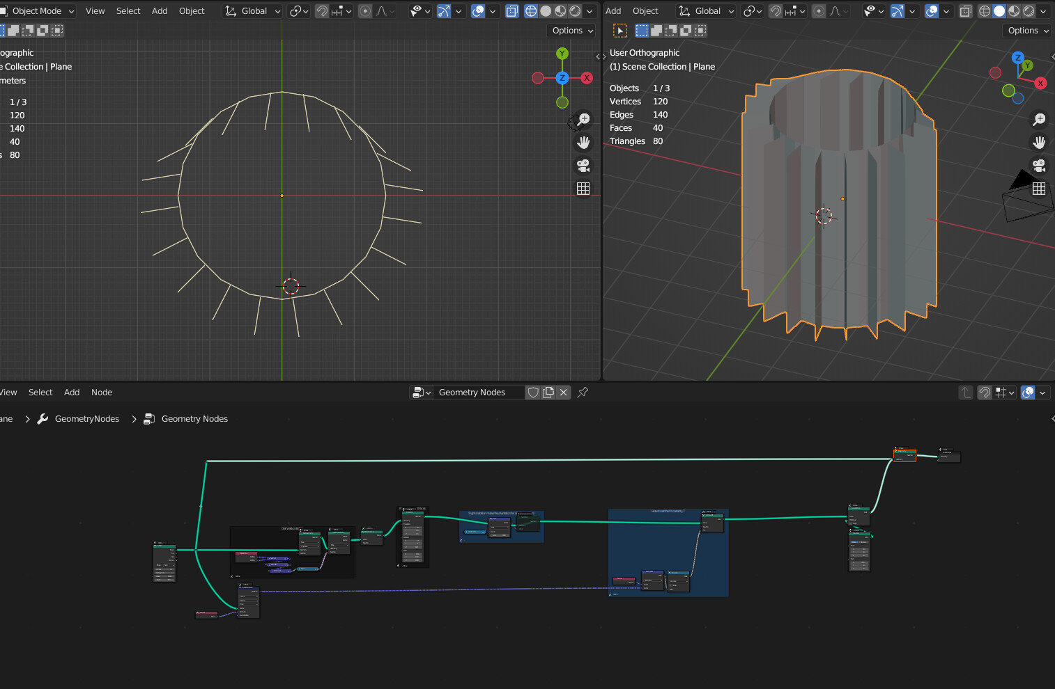
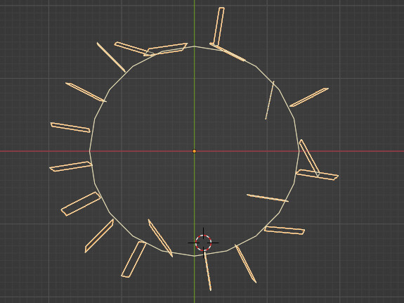
Here is my take on getting the poked lines :


I thought there could be a less hackish way, it’s probably not the optimal in term of performance , but it’s simple to setup : I remove edges by proximity with the original mesh.

And ok for the curve tilt ! I suck at math since school, it’s hard to get back at it, isn’t it ? :smiley:

If the ladders are instanced it’s indeed simpler as @zeroskilz pointed out, it’s like with regular instances, the curve tilt part shouldn’t comes to play.

But if you instance some curves and build the ladder from that , yes you need to set the tilt.
In my procedural house I added ladders, it’s some curves and I took the end point and snap it to the walls. And from that curve I build the ladder.
In that case I was lucky, because the ladder is oriented toward the wall the ‘tilt’ was set right without other issues. But if it’s straight I get the same issues as you have.

BTW @zeroskilz , you’ve got the jedi level with your ZCurve tilt node ! do you have some hints on how to fix this :


I think I can manage the negative rotation by trying random stuff, but once I activate some distortions on the curves everythings go wild :
image
Here is the .blend : Curve Tilt.blend (151.3 KB)
In the meantime, I’ll try every nodes combinations and see if that fix the issue :smiley: ( no that doesn’t sound like a desperate call for help…)

3 Likes

I don’t know about that… I feel stupid 99% of the time… and its rare that I do something useful the other 1% of the time when I don’t feel like a complete moron.

I see now the challenge when your curves and instances get generated from other things its not so easy to rotate them… hence the tilt requirement… The arccosine probably isn’t enough - guessing the arcTan2 will be required, so I don’t have a quick answer for you.

:thinking: About to go to sleep and busy tomorrow, but will attempt something when I get a chance.

3 Likes

hahaha maybe Luke Skywalker is effective 1% of the time also but that’s enough to save the day !
Thanks a lot for the quick answer, I need to learn more about ArcTan2 !
I’ll post an update if I find something !

1 Like

Curve Tilt1.blend (98.9 KB)

K, so, its got to do with singularities (when math goes to infinity)… it will all make sense when you consider that under default conditions (0 tilt), no single-segment-curve normal ever has a Z component, and a Z-up line-segment will have a default normal of (1,0,0).
image
… the solution is to “re-frame” the desired normal onto the plane described by the curve normal and the curve tangent-normal (the cross product (will always be a unit-vector orthogonal to the tangent and curve normal)).


… dot-products give the projections of the desired normal onto these two components for the rize/run parts of the arcTan2 (no magic, that’s all it does, you give it rize/run and it spits out angle - better than arcSin, arcCos and arcTan which has a operational range of -pi/2 to pi/2 whereas arcTan2 has operational range of -pi to pi)

Limitations of this method is that when the desired normal points along the curve tangent, you’ll get wild tilts again (can’t be avoided).

Thanks for this exercise - I think it may lead to other solutions that have been evading me.

Good luck.

2 Likes

Damn, you’re so strong !
I probably need to read it a few time again and play with the setup, but it starts to make sense !
And cheery on top, now I understand what ArcTan2 is doing !
Thanks a lot , this is so much useful !! You’re truly a 3D jedi !

1 Like

Jeez, stop saying that, I prefer it when ppl’s expectations are low. :roll_eyes:

Sorry if I’m not explaining stuff good, feel free to ask if stuff don’t make sense.

1 Like

Haha what a perfect example of Cunningham’s Law.

Thanks for schooling me and giving so much pointers to both of you, I’ll explore it asap and report back ! Cheers

@sozap I also noticed that tilt behaves very strangely with line curves that contain only two control points, but if you add one CP in the middle it becomes consistent and you can play with it.

2 Likes

Hahaha Ok ! sorry !
The explanations are really clear, it’s just that I have a hard time to understand and visualize what’s going on when it comes to math and vectors, I’ve got a lots of years to catch up :smiley:

I find that by swapping tangent and normal in the first cross product there is no need for the scale -1 on the normal :

That’s what I was doing before and it was failing in many places, because ArcCos deal with only a half of the full circle, now thanks to you it starts to make sense :
image
Thanks again !

2 Likes

Not surprised - my solutions almost always have bits still left-over from the “experimental” phase that can be simplified/optimized/removed. :+1:

2 Likes

It’s even better ! It helps to dive in it and understand what’s going on !

1 Like

Hmmm, be careful:


When you swap the order of the arcTan2, you’re re-framing with X-preference, but things are inverted now, so you’ll have to subtract from the curve-tilt for it to remain consistent (multiplying by -1 here like above):
image
without the times -1:
image

Good luck!

1 Like

Hey !
If you swap normal and tangent in the first cross product only, it seems to work without inverting the tilt.
Thanks for the hint ! If anything goes wrong I’ll look into that, I think I’ll use that setup quite often !

1 Like

Oh, right, didn’t catch that you swapped those… that makes sense now :man_facepalming:

Thanks!

1 Like

Seems easy to get confused, by trying to recreate the setup I messed up and inverting solved that ! That’s something that should be turned into a group so we can forget about that :smiley:
Thanks a lot for your time and patience !

1 Like

Done:

1 Like