rendered with 1000 samples.its moonys shader from post #173
here the link where i found the functions for calculating thinfilm
rendered with 1000 samples.its moonys shader from post #173
here the link where i found the functions for calculating thinfilm
I don’t think using Add Shader node is a very good idea in this case. There should be no additional light coming from anywhere in this case. Add Shader node should be used in case you want to mix translucent materials or something like that when a surface reflects light, but more light is added because it might come from behind of it. If you add glossy shaders, you can get reflectivity higher than 100% - a surface could reflect more light than it received. This is in most cases(I suppose it’s possible for a material to shift UV into visible light and seem brighter, but I don’t know of any cases where it actually happens) physically inaccurate, it might cause more noise or fireflies in renders and it can make your workflow a lot harder since materials like this might not act very predictably in different lighting environments.
I think it would be nice to see accurate iridescence added to Cycles one day. I also think we should not forget that all of the attempts in this thread are quite inaccurate physically and while they are certainly some nice ways to deal with this effect should not be confused as ‘the accurate way’ or ‘the correct’ or ‘the right’ way to mimic the effect.
It’s obviously a fake attempt to reproduce fairly well the phenomenon in a non spectral renderer. And Moony has tried hard to provide plausible values to play with (thanks). It’s a bit like the fake caustics trick for refraction. They are absolutely fake and inaccurate, but if you throw them in a scene, the are most of the time ok, they work in giving theright caustic look. Often, only looking at real caustics you can tell the (big) difference.
Indeed.
What we have to consider when talking about iridescence, micro-roughness etc. Even though our node groups are not physically accurate…from an artistic perspective, does the scene look better if we use these non physical simulations than if not.
Pretty much everything cycles does is not physically accurate. In the real world, cameras don’t shoot light rays. A rough glossy surface is due to real physical roughness, not simulated by a GGX microfacet approximation - and certainly not by an anisotropic BDRF. Refractive mediums are solid entities, not infinitely thin surfaces. Real glass doesn’t use “is shadow ray”. Real caustics don’t “filter glossy” and real light is not made up of just RGB components.
If Cycles gives us access to light vectors at some point then we may be able to build an even more accurate model.
The point is however - does an effect that looks 80-90% accurate look better than if we don’t add it at all? If the answer is yes - then we are closer to our goal.
well said.what we need is a group node to parenthisis calculations at least.
@MartinZ replace the addshader with a mixshader ,simple as that.
Just been doing some maths in excel.
It looks like the values I chose for the wave texture scale for the RGB components in order to match the color ramp in the colorpy screenshot have a direct relationship with wavelength.
The wavelengths I took for RGB were from this website:
Red = 650nm
Green = 510nm
Blue = 440nm
If you plot these wavelengths again the natural log of the scale factors - you can fit a power curve to the data with a very good fit.
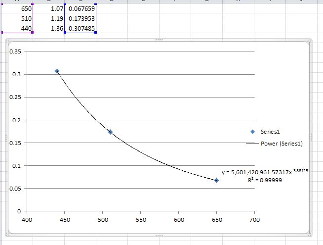
Still need to figure out how this relates to IOR - although looking at the ColorPy code - it does give some equations for the phase shift and reflection coefficients.
(n1-n2)/(n1+n2)
and
-2 * thickness * 2 * pi * n2
Need to go through the code a bit more.
Oh cool, this solved then also the world’s energie problems.
oh, if it really could!
i think at line 132 the aproximation is explaned
c&p
[TABLE=“class: highlight tab-size js-file-line-container”]
## small-reflection approximation
[/TABLE]
#R = self.R12sqd_plus_R23sqd + self.R12_times_R23_times_2 * math.cos (self.phase_factor / wl_nm)
since we need sine function for the wavetexture,cause not cos func is available
i changed the phase_factor to
-2 * thickness * n2
to get the sine value (im not sure about the -2)
i deleted * 2 * PI, based on this page
moony you choose your n1 ( IOR )for lightray before hits the thinfilm ( i guess for underwater you chosse 1.33) so i this case our light travels through air witch has a IOR (n1)of 1
n2 is the thinfilm self ,for soapbubble is made with water your IOR n2 is 1.33
n3 is the material that is represent the base materiallayer under the thinfilm .for the soapbubble its air again with ior 1.otherwise for a plastic for example you would choose n3 IOR 1.5 ect.
i the end you get the reflectionspectrum from the IOR combinations,thickness and wavelenght you choosed.is well explaned in the github code
edit,i think i know what you mean
now the wavetexture color is based on the thickness on the x-axis
what we need is the color based on reflection angle to get more usefull values
Oh, come on… Cameras don’t shoot light rays in Cycles. Rays are just traced from the camera. Cycles is not meant to be physically accurate renderer. However physically accurate calculations in case of iridescence would give us some benefits. For example - more realistically looking reflections and more realistic look under different illumination. Since at the moment this is not really practically achievable in Cycles, I think a simple color ramp in combination with careful observation of real materials is the best approach to recreate this.
To be honest, I fail to see the benefits of splitting the color ramp into RGB components and using less accurate representation of the RG and B values with sine wave textures instead. This seems to be more demanding in terms of computing power and less accurate. Also if formulas for calculating light interference are needed I think it is logical to take them from physics. It is not hard to calculate light interference for thin films for light of particular wavelength. What is difficult is to put that into the context of Cycles scene. It seems we do need features that do not exist yet for that.
Perhaps - but that still doesn’t invalidate my point - tracing rays from the camera is not how it works in reality - it’s an approximation to make the calculation speed acceptable (but leads to obvious flaws in the image - like fireflies).
Physically accurate iridescence would be an advantage - but we cannot recreate it since we don’t have access to the light vectors - that’s the reality at the moment - so we have to come up with a reasonable compromise until such time was have access to the correct tools or information.
I’m not sure I understand your point. My sine wave approach was based on the ColorPy graph - and with the correct sine wave scaling factors gives pretty decent result IMO - I have been able to recreate the colour ramp from the ColorPy website pretty accurately
You could argue “why not just sample the colour ramp” and TBH this is the approach I took originally - however splitting the RGB components into their respective sine waves does have the advantage that if we can understand the relationship between IOR and sine wave scaling (in essence simulating the phase shift that occurs and therefore constructive and destructive interference between reflected and refracted rays) - we could in theory recreate thin film from any arbitrary material and IOR - whereas the hard coded colour ramp method means you are fixed to that particular material - and need a colour ramp to sample in the first instance (and there are very few about - I have been looking).
In terms of taking calculations from physics - that’s kinda what i’m working towards. I have so far been reverse engineering - however I didn’t now about the python code calculations until a few posts back - so they may help attacking the problem from the other end.
I’m all about exploring options - and I have presented three different approaches so far - which one you want to use (if any) is down to you and your own artistic interpretation. In the mean time i’ll keep working on it and posting my results in the hope we all learn something.
python could allow to use complex number and get a better model
but we don’t have access right now to python coding with nodes
may be in 2.8
happy cl
Complex number math can be expressed using regular maths. No “absolute need” for complex math libs, they only makes life easier. The easy Mandelbrot/Julia set z=z²+c translates to x=x²-y²+a and yi=i*(2xy + b). You could possibly derive something similar (but a lot more complex) for the magnetic versions, but these would be so complex to solve that a complex math lib would probably be useful. I solved it using maple ages ago after giving up after several sheets of paper, and I’m like; seriously, wtf? ![]()
Basically, complex maths can be set up using regular nodes. Libs only required if solving gets really nasty. I made mandelbrot texture using nodes (although it stopped working after about 9 iterations - shader compile would fail or something).
No problem using Add shaders if you control what goes into it. I.e. white glass can be white glossy and refraction mixed with fresnel, or fresnel and inverted going into respective colors and then Add Shader in the end.
Everything that’s hit, shoots rays in Cycles  as in reality every atom that gets hit by a photon shoots another, a different one out (or an electron). Such are theories. The fact that everything is a mix of mater, fields, super strings… “the closer you look at it, the more likely it is to disappear” makes for a fact constant uncertainty (principle). Thus making everything impossible to observe in real real-time. So everything is simply an approximation within the band of tolerance, a compromise.
This (moony’s & the accompanying blenderhead collective) tests & experiments make perfect sense. It feels delicious & healthy, so enjoy the blending with chef who has good taste. It’s almost like a festival to complexity using only simplicity.
How else would we learn about all the dishes and become experienced cooks ourselves otherwise? Maybe same as in dark ages - stay silent & wait for God to judge, intervene. :eyebrowlift: (rhetorically)
PS
Really good CarlG
Found some more websites/papers. In the first one - the guy calculates the phase shift of RGB components and plots out sine waves exactly as I am attempting to do.
http://laser.physics.sunysb.edu/~ett/report/
http://www.schoolphysics.co.uk/age16-19/Wave%20properties/Interference/text/Thin_films/index.html
https://www.physics.ohio-state.edu/~kagan/AS1138/Lectures/14_interference.htm
i think we need to find out, how make a wavetexture, based on reflectance angle from 0-90°.
this we could put into a layerweight node, for display all colors ,depending on viewangle.
and on top ,we could give this shader,a fresnel for the reflection intensitys.
edit,or better
if we know, how to make the color, based on reflection 0-90,maybe we find out, how to make a wavetex ,based on intensitys ,for the given material what we want to reproduce.and use the intensity tex for multiply and not a fresnel fac.
so we would have color on reflection angle and intensity.and we could calc any material want for this.
edit,maybe the colorpy codes can give us some hints.i think i saw textures based on intensitys on the colorpy page.but the most needed is the reflection 0-90 color wave.
So, if I understand you well, with a colorramp we are bound to a single IOR, since a different IOR would require a slightly different colorramp. But, for the sake of simplification, or approximation, how much variance in terms of material can we find around us? There’s water/soap for soap bubbles and oily water pools (i guess ior 1.33), then there are coatings for solid materials like leather and metals (and i guess ior around 1.45). It’s not much of a difference, or am I missing the point?
I think at the moment it might be impossible to do it in Cycles much more accurately than the color ramp approach. What we saw in colorPy was for uniform white illuminant, as opposed to the environment the objects are actually in. I think no matter how accurate the math or the formulas can be, without getting the spectrum that actually is illuminating the surface and getting the actual directions light is reflected off the BSDF no matter how complex the calculations can get, it is not going to make it possible to simulate the effect any more realistically in practical situations.
What am I saying? Should we all stop rendering immediately because of that, throw our computers out of the window, quit our jobs and start looking for new passions in our lives other than computer graphics? No. I am not saying that. I would however like to direct everyone’s attention to the possibility that it might just be more logical to base our decisions replicating iridescence in Cycles on actual observation of materials in every case when we try to replicate the look of them and not on IORs or thin film thickness or light interference. While this does make a lot of sense in spectral renderers like Thea, Maxwell or Octane to control this effect with IOR values and thickness of the thin film, I think at the moment it does not make that much sense in Cycles where a more ‘artistic’ approach would most likely give more accurate results.
There can be a difference. The IORs of all 3 materials matter. See Khan’s Academy’s lectures on thin film interference. The color gradient from colorPy we are discussing is also only for flat white light. So if an object reflects say another object, that is red, it should behave differently at that point. Oh, and also its only for sharp glossy shader, rough glossy surfaces will scatter the light in different directions and will also change the effect.