another approach with modulo

The ideal would be to be able to specify a film thickness and an IOR and the shader be able to spit out the correct colour.
That’s essentially what my shader in post #129 does - although the colours (and as a consequence the IOR) are hard coded into the colour ramp. All my shader does in that example is use the thickness value to drop the shader down onto the correct part of the colour ramp.
My later tests are an attempt to simulate the underlying physics of constructive and destructive interference using sine waves for each RGB value. If we can accurately reproduce the newton rings for each RGB value for a given film thickness and IOR - adding them together should result in the correct iridescent colour spectrum (or as good as we can hope to achieve in a non-spectral renderer).
I am kinda getting there with the tests I did in post #148 and certainly at the start of the iridescent spectrum, the colours look pretty close and in the correct order - but the values I am inputting to scale and offset the RGB sine waves are arbitrary at the moment and don’t translate into physical film thickness and IOR values (i.e. I cannot just take the IOR and thickness of silicon dioxide, plug it into my node group and it give the correct colour as per the earlier paper.)
1 Like
Are you plugging R, G and B patterns to separate glossy shaders and adding them together? Would we avoid the need for outgoing vector for rough glossy materials this way if we used the precalculated color values like these?
[ATTACH=CONFIG]490327[/ATTACH]
No - i’m creating a layer weight driven sine wave pattern for each RGB to simulate the constructive and destructive interference for each colour at different viewing angles. I then scale them so they overlap at different points (like in the above graph).
I then add these three sine waves back together using the combine RGB node - running that resulting colour into a single glossy shader.
This results in colour bands equivalent (or that’s the theory) to the colour ramp shown above the graph. I was trying to demonstrate this equivalency in posts #148 and #149.
This would allow greater control over having a hard coded colour ramp - since simply changing the scale or offsets of the sine waves would allow us to create different iridescent effects on the fly.
Interesting - but doesn’t modulo give more of a saw tooth pattern, rather than a sine wave?
yes but i pass the normalized result (0-1) into a sine like ramp where 0 and 1 have the same value ![]()
By carefully tweaking the scale factor on my wave texture node setup and matching the peak locations on the graph above - I have been able to get a really good colour match to the thin film soap bubble colour ramp above.
This is a screenshot of my result combining RGB sine waves (top pane) - versus a screenshot of that colour ramp from the paper (bottom pane).

There are a couple of minor differences probably owing to the fact that my sine waves are all of similar intensity - but overall i’d say it was a good match, all of the band locations are correct and are pretty much the correct colour.
My wave texture scale factors for this were
Red = 1.050
Green = 1.190
Blue = 1.390
Ok - getting somewhere now.
I still haven’t figured out the relationship between IOR and sine wave shift - but I have been able to create a material based on the above generated color gradient and have been able to tie down film thickness to a physically real value.
This this nodegroup - specifying the thickness in nm will give the correct surface colour for a film of that thickness. Specifying a non-zero width (in this case I have set it to 1) allows the apparent thickness of the film to also change based on the viewing angle - therefore at larger angles, the colour of the light will shift to the right.

In this case - the film of thickness 100nm gives an off white/yellow hue to the facing angles - whereas the width parameter allows the apparent thickness to increase up to around the 220nm mark at glancing angles (I may have a play and see if I can make the width value a bit more sensible).
i think in theory you must take the wavelenght freqency into the math for more accuracy
i guess now you have your ior from the sine node you have allready posted.but this is just a color with the ior (sine) without freqencys.but different colors have different frequencys.that would explane why it doesnt match perfectly and have that shift.
if im not wrong
based on average freq of 442 thz for r ,566 thz for g ,650 thz for b
based on r 1 ,g has a freq that are 1.148 ,and b 1.47 times higher than r
or based on b 1,g has a frq 0.87 ,and r 0.68 lower frq than b
maybe that can used as multiplicator ,but dont ask me how.i guess after the sine function,but that is just guess.
Ideally yes - however the paper on which i’m basing these tests was conducted in RGB colour space.
Just created a couple of animations to show the results of the shader I created a few posts above.
First animation is varying thickness (from 100nm to 1000nm) - with a constant width value.
Second animation maintains the thickness but increases the width value
wow :eek:
Got off-track for a couple of days and BAM! moony, you’ve given some TLC to iridescence. Right on :yes: looks really plausible.
thanks
BTW
Which of the posts ‘above’ shows the shader?
Post #168 for those animation tests. Here is the blend in case you want to have a play.
The main parameters are:
Thickness - this sets your position on the calculated colour ramp and corresponds to a real world thin film thickness in nm - valid values are 1-1000
Width - this specifies how wide you want the colour dispersion to be, again in nm. So a 100nm thickness with a 250nm width will show facing colours specific to a 100nm thickness film and glancing colour specific to a 250nm thickness film.
The other two parameters don’t worry too much about
Blend - this modifies the facing falloff curve (valid values 0.1 - 1)
Peak shape - this increases the peak sharpness of the sin wave (valid values 0-100). A value of 1 is the standard sin wave - and increasing values will sharpen the peaks leading to less overlap (at a value of around 20 - the RGB components will separate - leading to no overlap).
Attachments
irid4_accurate.blend (679 KB)
this is realy great moony,very usefull
here my approach ,with your shader ,to simulate a soapbubblemonkey
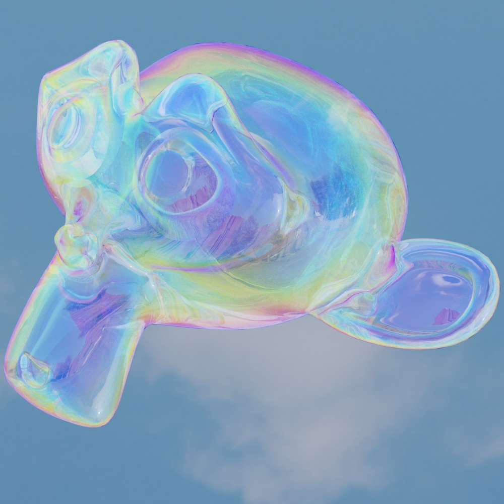
edit,have set the width same as the thickness,to become more colors. made air ior for the main film material shader and water ior for reflection material,as seen in most papers for soapbubbles and combined with a add shader.simple as that.
rendered with blender filmic and very high contrast setting.render before was with basic contast
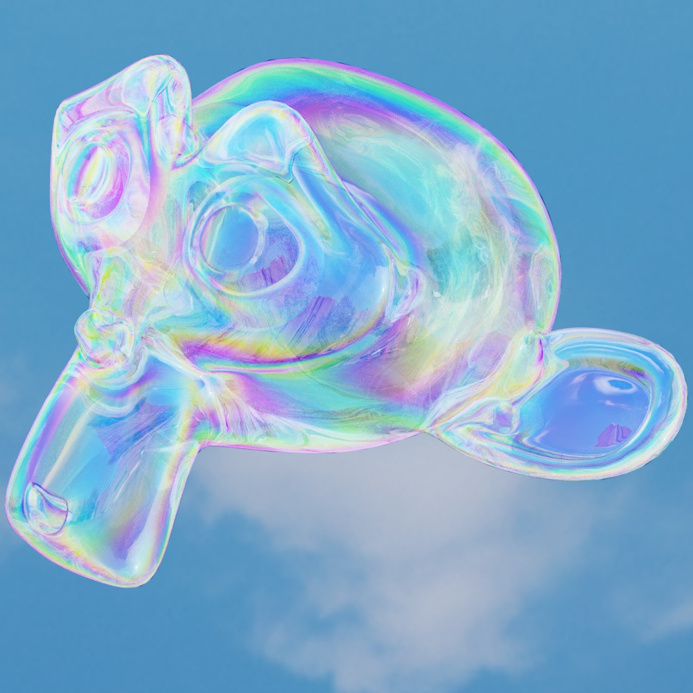
edit,getting realy nice materials with it
variation with thickness and ior values.material used is mainly glass shader

1 Like
Thank you for your kind gesture, am really interested to take a look. Now i only need some dedicated time or a bad weather to lock me in.…
![]()
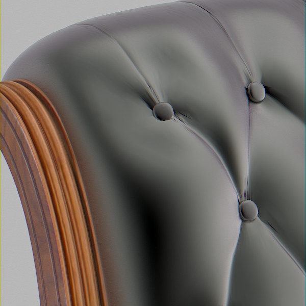
Going back to what MartinZ said earlier in the thread about iridescence making a difference in archvis on things like leather - I decided to try my node on a leather chair (credit to Blendswap user eMirage for the model and materials). I have modified the leather material slightly - to change the colour to black and add in micro-roughness too. I have also mixed the iridescent node with a colour mix set to white (85%) in order to mute the iridescent colours.
I have attempted to create the leather chair test from the microfacet iridescence video poster earlier in post #109 (at time index 4mins).
I used the iridescent nodegroup I posted a link to a few posts up with a thin film thickness of 730nm and a width of 150nm.
Here are the test images with and without iridescence - the iridescent one looks pretty close to the video.


A zoomed shot showing the iridescence close up.
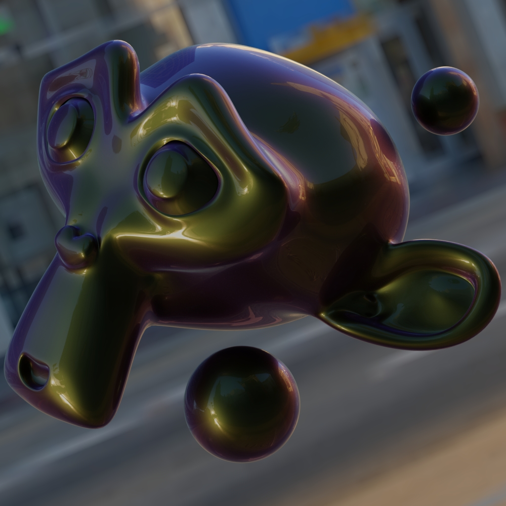
my attempt to reproduce the carpaint shader form the paper.i set thickness to 505nm as in the paper,and width to 150.i dont get the cyan like color.so i guess a different colorwave spectrum was used.
but looks like a nice start anyway.
You probably need to up the width. If you look at the colour ramp in post #163 - the cyan in that part of the ramp occurs at around 700nm.
With a base thickness of 505, you’d need to set your width parameter to at least 200 in order to see it.
Another way would be to increase the blend parameter from the default of 0.5 up to around 0.7/0.8
Looks like a really nice material - care to share the noodles?
sure
here my next try .i think im getting closer.
have a tip for all they try out moonys shader to control the colors
first set blend to 0 and use the thickness for control the F0 reflectioncolor.
then set blend to 1 and use the width control for rimcolor and wavespectrum width.(start at 0 and go higher)
then set back the blend to 0.5 and voila thats it.
you can finecontrol the intensity from the color, with the peaks sharpness at the end if you want.

here the noodle.i have used costum wave scales for this.i calculated the colorpy function and feeded the values i get in the rgb wavetexture scales.
r -2.132
g -2.534
b -2.858

1 Like
looking nice
any sample fie available for this
at what samples was it done ?
happy cl