Is there an easy way for us to use that?
While we’re on the subject of thin-film, the Arnold engine has just added this effect to their standard material feature-set (with good reference material)
https://support.solidangle.com/display/A5AFMUG/Thin+Film
Since Arnold is an RGB renderer, it might be possible to recreate it with Cycles nodes using nodes such as the color-ramp, RGB curves, color mix, and the math node. The docs. also state that this would be something you have in your tree before you create the glossy coat.
About (offtopic) PBR thin film interference, in case you had not seen it, here with OSL (CPU);
https://blenderartists.org/forum/showthread.php?403299-UPDATE-v1-6-Cycles-PBR-thin-film-interference-and-metals
^^ already posted
Oops, sorry…
Thanks. I mistakenly thought it was actually doing a bit more than what it is (I thought the n=1.2 and n=1.5 were generated from the node setup - not the basis for it).
Found some papers on thin film interference - might be of interest:
How about this as a first approximation. I created a colour ramp based on figure 6 in the first paper linked above.
There are three inputs.
Layer weight - sets how steep the falloff occurs.
Thickness (nm) - is the thickness of the iridescent layer in nm (values between 0 and 1000 are valid). This setting essentially determines where on the colour ramp you are.
Variation - this determines how much the apparent thickness changes with viewing angle (essentially it’s how wide a slice of the colour ramp you are taking). A setting of 1 incorporates pretty much all of the colour ramp - and you will see banding. The best settings are between 3 and 10 IMO.
You can add variation/noise to the iridescence by multiplying either of these values with a texture.
Attachments

Irid1.blend (564 KB)
Who is actually the developer of the cycleshader we already have?
I had a video yesterday saw how someone programmed an absorption shader with osl.
If I remember rightly, we have something later exactly this absorption shader function, in a subsequent version in
cycles get.
Is it not better would we try to develop the diffraction shader and the iridescence shader on the basis of the paper
we have in osl itself?
So then the dev of the cycles shader can then integrate these into cycles as gpu shader, as it happened with the
absorption shader?
But you could try to start common osl project thread for it, and only for these two functions together to develop an
osl shader.
Ultimately it is better to try this way ,because we have all the possibilities to implement all formulas
mathematically, exactly as described in the papers.
Here the video to the absorption shader, here you can see how a simple equation can be so effective.
it could possible ?
That’s very interesting. Khans Academy has lessons about thin film interference. I cannot wait till I get a few spare hours to have a look at some papers about integrating it to 3d. Cool. I think If Cycles got integrated correct solutions for effects like these it could be a huge step forward. This can be the selling point for many 3d artists when choosing a renderer.
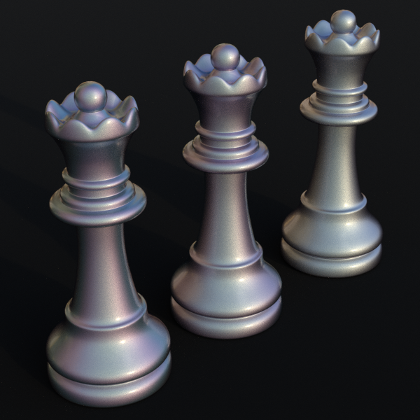
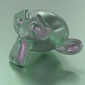
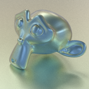
A test render of my node setup above. Same film thickness (350nm in this example) - but different variation values.
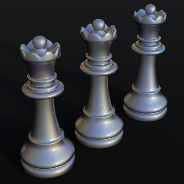
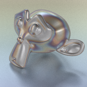
And again at 600nm
This looks really great. What is the color ramp based on?
The measured colours of a thin layer silicon dioxide from figure 6 of the first of the three papers I liked to a few posts back.
I have also done a colour ramp for the Si3N4 layer too.
I haven’t looked into this in depth yet so I might be missing something here. So the actual effect is different depending on thikness, IOR of the thin film and the material behind it (assuming we are allways observin it in air), right? But it can be kind of ‘baked’ into a color ramp? What if we had an OSL shader that could be baked to a color ramp for GPU rendering?
I guess this might be good enough already as I doubt I will find all the info about the thin film on a specific leather some sofa is going to be made of and it might not differ enough for it to matter. ![]()
How about a different approach.
In this case - I created 3 colour ramps (R, G and B) based on this graph from the link below
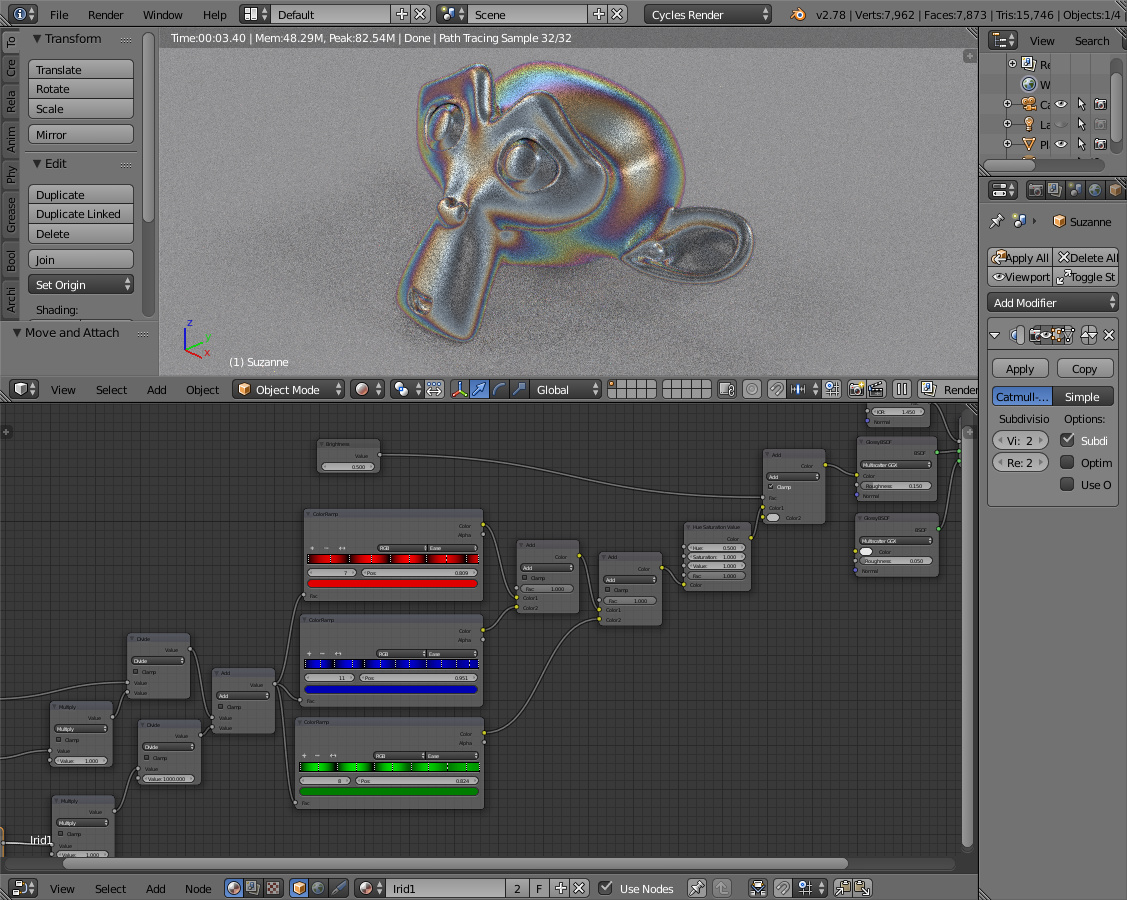
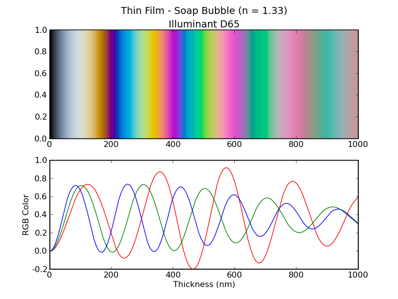
http://markkness.net/colorpy/ColorPy.html
I then added them together using the layer weight node key the observed thickness as a function of viewing angle.
I wonder if it might be possible to recreate the graph using a simple math function for each RGB component, rather than using colour ramps. The three RGB components appear to be based on a sine wave with a bit of modification at the start and end.
Perhaps a sine function multiplied by an RGB curve…hmm have to think on that one.
1 Like
In essence yes - the colour ramp in my material node is specific to a thin layer of SiO2 over a silicon substrate only.
Other materials would look different.
very nice!
Following on from what I said in post #136 - it does seem like it may be possible to recreate the general RGB graph using math nodes instead of colour ramps.
I have made a start on it - but it’s still not right since currently the sine waves are all the same size. Looks pretty nice though and you can get an almost infinite variation in colours, bands etc by changing the wavenumber, separation and layer weight parameters