I wish to create an animation of light pulses moving around an optical cpu, however my experience with Blender is very small. I thought since this is a large project for me it would be a good idea to get some tips to get me started on the right track.
Since eventually I intend to animate light pulses moving around the waveguides or tracks in the figure above, is there anything I should be doing at the modeling stage to save time later?
Not sure about the animated pulses but as for the surface an overhead shot of the chip used as a dispalcement map on a heavily subdivided plane ought to do the trick.
Thanks mate, that is a much better way to do it. The only potential problem is I need it to be very accurate and smooth, so it might take an ungodly amount of polygons to do it properly. I’ll probably be running with an at least 1000x1000 pixel image, with the smallest features being about 5 pixels across. Only one way to find out if it’ll work though.
For the light pulses I’m planning on using one of the many light saber tutorials people have posted. I have no idea how to animate things in Blender, but it can’t be too hard to get the pulse to follow a curve.
I tried different combinations of subdividing the plane and subsurface modifiers, and I ran a gaussian blur over my source image. This is what I got: http://www.bitflicks.com/chip.bmp Edit Just to clarify, I ran out of memory at this point and so I couldn’t push the subdivision pr subsurface modifier any higher.
Am I missing something? Or does anyone else have a suggestion?
Are you rendering with the options labeled “Save Buffers” and “Free Tex Images” enabled? Both of these will help you save memory by saving render tiles to disk rather than holding them in ram and removing from memory prortions of the texture images that have already been rendered (at least I think that’s how it works) I’m 100% positive that both of these options are there to save memory just for situations like the one that you’re in. If all else fails you could also try using the texture as a nor map which should be convincing enough as long as you dont view it from too sharp an angle or build up a little bit of geometry around it or maybe you could hide some of the rough edges by placing a nor map over the top of the image you’ve already rendered and relight in the nodes compositor via a normal pass which will yield some Truly Wicked lighting effects. The last technique is really bad to the bone and can result in some brilliant metallic effects if you play with it long enough. Give me a minute and I’ll upload a few images.
Ok, in the first 2 image sections you can see how changing the direction of the normals changes scene lighting. In the third section you can see how to add a color cast to the light. In the fourth section notice how I seperated the blue plane from the cubes via render layers. This isolated the normal pass that I applied to the cubes so that it did not effect the blue plane. The fifth section shows what to do if you want to uv map an image texture to your model and use that image as a normal pass. When combined with the normal lighting scheme in the nodes compositor, this is where you can achieve some truly STUNNING visual effects! This works best when your image textures are color. For some reason (in my experience) B&W images just don’t cut it for nor maps, but maybe other users can share some different experiences with you. The color images will also allow you to produce those really candy, metallic images that I mentioned earlier. And they’re way cool if you’re going for a fairy tale “Hansel and Grettel” look. Sorry for not posting images of the above but I don’t have any in this computer, they’re a bit more involved to set up and render, and most of all I’m not very good at it but have been having insane ammounts of fun with the technique. One thing to note is that after you have rendered a layer the normal passes are applied as a POST process meaning that they update on the fly as you move the nor dot around in the nodes compositor which means you don’t have to re-render the layer in orderr to see the effect when you change the normal position.
Thanks mate, I appreciate the trouble you’ve gone to. If I can get to something as nice as your 4th image I would be a very happy man indeed.
Is it possible I could have a look at the .blend file for the 4th frame of the image your posted? I’m having a bit of trouble working out what you’ve done (I’ve never even used the left most panel in your attached images). Are you still subdividing a plane and using a displacement map, or is this purely a normal mapping technique you’ve used?
I tried turning on the options you mentioned to save memory, and I could just get to an image I could be happy with, however the test image I’m rendering is only 1/00th (by area) of the image I ultimately want to render. I don’t think displacement maps will work for me.
Thanks mate, I have to admit I had some trouble following what you did. Nice effect though.
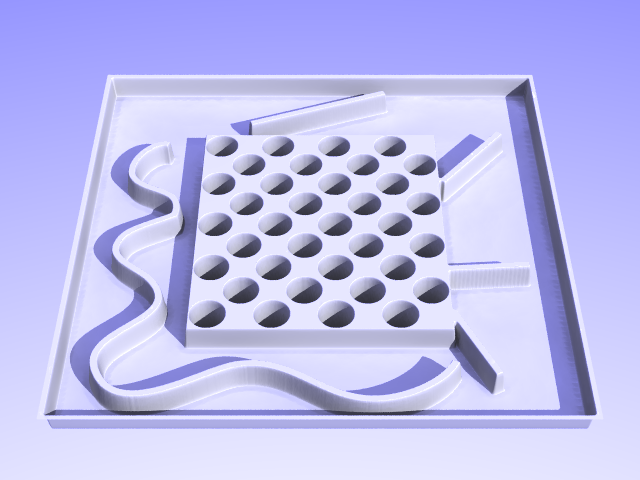
In the meantime I had a go using my old favorite POV-Ray, and I got a result I’m happy with. This image (without the radiosity) takes about 5 seconds to render using only a few megabytes, and is a better result than I think I can get from Blender. It uses POV-Ray’s height_field technique, which I assume is roughly the same as Blender’s displacement mapping, although the results are quite different. I think it works better in POV-Ray because POV-Ray samples the image directly to generate the mesh, as opposed to generating the mesh in Blender and then sampling the image.
A bit more tweaking and I should be good to go. Only problem now is doing the animation will be a pain in POV-Ray.
That looks really nice…I downloaded POVRAY and was completely intimidated by it’s interface so I’ve never used it.
I can’t say enough good things about Blender’s nodes compositor. It is absolutely worth any time spent learning how to use it. You may want to model in POVRAY and then animate in Blender, finally compositing the animation in the nodes compositor.
There is no disp map in use in the above images, only cubes and render passes via render layers. PM me with your e-mail address and I’ll be happy to send you some more sophisticated files to studdy.
Well, he got a a really cool model by rendering in POVRAY with much less hassle than he was running into in Blender, so…Render in POV via camera moves and basic model structure that were that were created in Blender, use a a copy of the model back in Blender to set up paths over which animated halo material meshes will travel (pulses), render out using the same camera moves but don’t render the model, import both animations into Blender’s nodes compositor, do composite. Viola.
