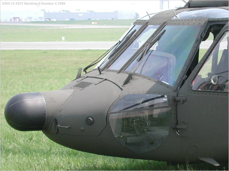
I would use a union boolean to add that nose piece. It’s a perfect candidate for that. First get your main mesh looking the way you want it with subdiv modifier added (but not applied), and then add the nose piece and clean up the mesh where it joins in order to preserve the curvature around the join. The important thing is to make sure you have enough edges on the main mesh to accommodate the edges on the nose piece. The nose piece doesn’t have to be the standard 32 segments. Reduce it enough to make the join without having to add a bunch more loops on the main mesh. Subdiv will still retain the roundness for you.
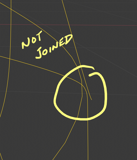
Also at each junction of your curves there isn’t a vertex… things like that will play havoc with you when trying to skin this. I don’t know if it was just the obj file export or not, but I would keep your original curves as curves to help in getting things smooth.
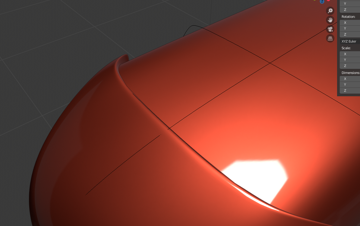
The problem i have is that at the bottom of the model, there is a smooth transition from the main body part to the nose part.
If i now split the base and nose part and then boolean them together, then there is a ridge there because i cant exactly line up both parts.
This ridge then causes problems when shrinkwrapping onto the combined mesh.
Is there a way to line up both parts at that point?
That nose part looks like a separate piece that is riveted on…do you really need to connect it to the main body?? Just snap the points to the surface and save some time…just my two cents.


")