Hi, I want to create a height map from a 3D model in Blender using Blender 2.8 and Eevee.
I cannot find tutorial on how to do this. Does someone know of one?
Hi, I want to create a height map from a 3D model in Blender using Blender 2.8 and Eevee.
I cannot find tutorial on how to do this. Does someone know of one?
You want to create a height map FROM a 3D model, not FOR a 3d model? You create height maps from 2D textures, so if you go to Orthographic Top (Num 7) and take a screenshot or get a render, you’ll have a 2D texture from above you can convert to height/normal/displacement/whatever with Njob or AwesomeBump or your preferred software.
Thanks Joseph. There’s a way to use the Camera in Blender and add material to my mesh, then set the material to “Shadeless” and then create a black and white render. I have seen a video of his but can’t find it anywhere. I think it would be a similar process for making a black and white “displacement” map from a mesh. Anyone know of such a tutorial?
I bet it’d be easier to do this in compositing from passes, but last time I did this, I used:
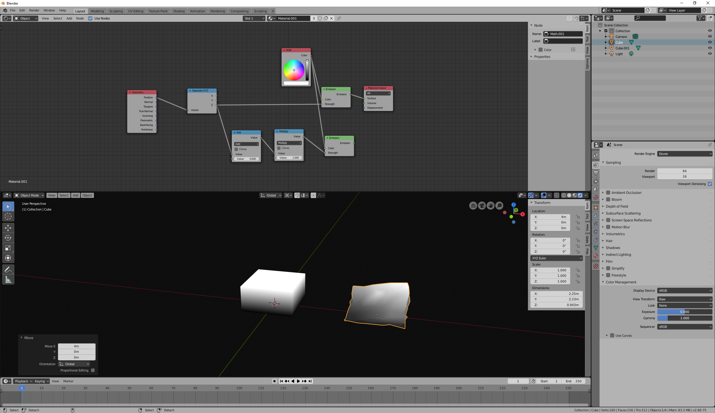
Custom material: geometry/position->separateXYZ.z->emission.
Orthographic camera.
Raw color output.
You can render that in Eevee or Cycles, doesn’t matter.
bandages, interesting. Yes that’s probably what I’m looking to do. I am using an Orthographic Camera and just trying to figure out how to set material to shadeless and using a node to better show the depth of the mesh but I have no idea how to set up it all.
Emission is shadeless. Although in Eevee, emission is probably redundant, don’t even need a shader if you want emission.
Nodes are just like what I said. Not so complicated. Showed an alternate path for transformations you may want. At default, it will show depth from 0,1 range.
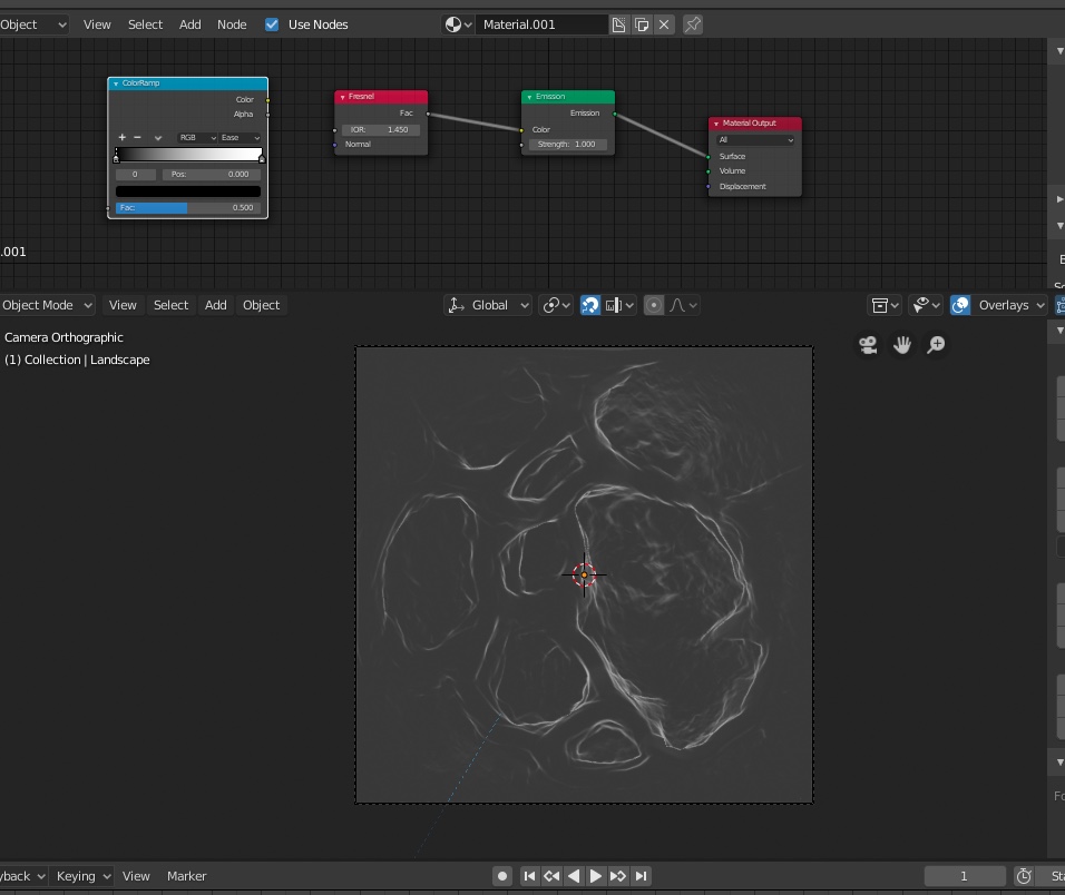
bandages, Hi, I think there’s a simpler way. I remember the tutorial used a fresnel node and a emission node but something’s not correct. There needs to be a way to darken the blacks and adjust the whites/greys for a proper height map. Any ideas?
No, do not use Fresnel. That will not give you a height map. (It will give you a map of slope though.)
If it is not black, it is because it is not at Z = 0. That’s why I made that alternate path with add and multiply nodes. Add on offset, multiply a scale.
If you want a height map, do not adjust the grays. What I provided is a linear map of height, when rendered with raw color. If you adjust the grays, you will no longer have a linear map of height.
bandages, ah ok, makes sense. Your nodes work great! Thank you! ![]()
Question: I used the RGB node as-is and didn’t adjust the slider. Is it necessary to adjust the RGB slider to adjust the peaks and valleys or should I leave the RGB in it’s default state?
Next Step - I will render the height map and then see if it matches my sculpt. I will post the results.
You need to think about what you’re doing in terms of math. The color that you get is equal to world space Z position of the mesh, times the color. If you use a gray color, then that’s the same as squishing the mesh, or multiplying the height. They’re all the same thing. It’s all just numbers. It’s all just math.
In reality, I would have just plugged Z in Color rather than strength for the emission, but that can be confusing to people that are starting out, so that’s why I showed you the way that I did.
bandages,
One and done! I plugged the Z in Color for the Emission strength and got rid of the RGB node! Thanks. 
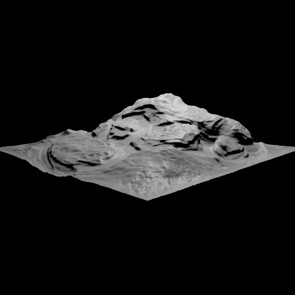
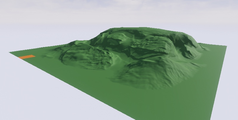
Here’s the sculpted landscape in Blender. I am trying to replicate this in Unreal using a Height Map created in Blender.
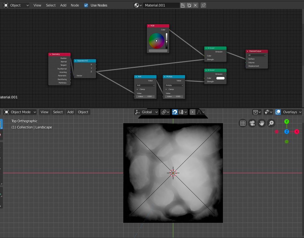
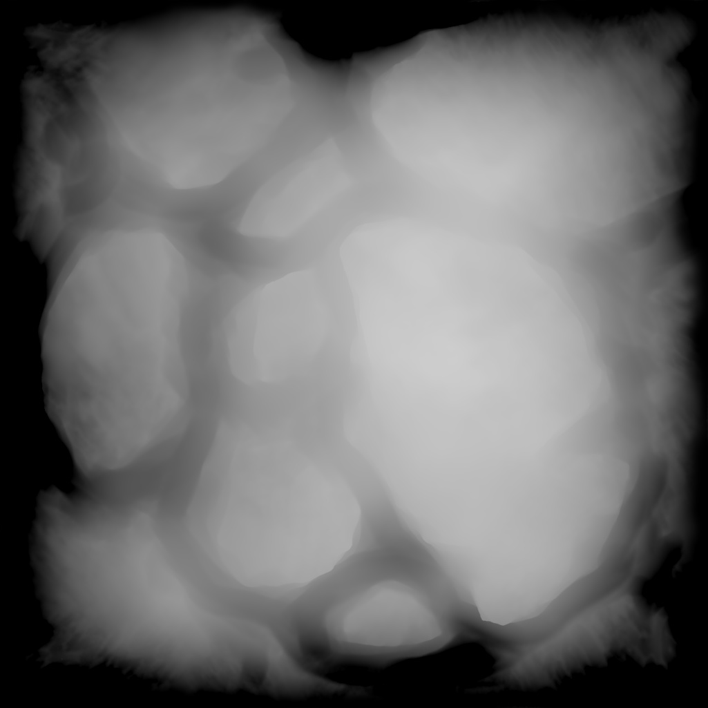
Here’s the Height Map Created in Blender from the Blender Sculpt above.
Here’s the Heightmap Applied to a terrain in Unreal
As you can see the edges are far too sharp.
Questions
How would I increase the contrast in the node settings so the Height Maps Darks and Highlights show more pronounced peaks and valleys?
Is there something I can change in the (Node Editor Settings) in Blender so where the edges meet the ground there’s a smoother transition?
It looks like the standard “render z pass” is busted in blender 2.8
it works like a charm in 2.79b
i just rendered a z-pass in 2.79b and i got a depth map
then opened the *.blend file in 2.8 and the zpass rendered as the combined and NOT the zpass
the blend file, but it is 114 meg
JohnVV, Hi, thanks for the file but tried to download file but said “Missing DNA Block”. Is it a Windows file? I’m on Mac… I’ve been playing around trying different nodes to soften the edges and increase the contrast. Added a Power node and a Color Ramp and think it’s looking a bit better now. ![]()
Blender Sculpt (This is what I’m trying to achieve)
A better result (below) after adding a Color Ramp and Power Node but still not getting the same “peak” at the top because the nodes are blowing out the whites. ![]()
If someone can do a super quick simple sculpt then post their file I’d really appreciate it. I was really hoping the Height Map could reproduce the terrain more accurately and I don’t know what I’m doing wrong. ![]()
Are you rendering in raw color? You talk about using power functions-- you shouldn’t have to, unless you’re not rendering raw color.
You’re not just blowing out your whites, you’re blowing out your blacks as well. That’s the point to the add and multiply nodes I showed you-- you need to rescale your position.z to the 0,1 range. Is the lowest point at -1 and the highest point at 3? Then add 1 and then divide by 4. (Or else just scale your mesh so it lives in the 0,1 range of z values…)
- Are you rendering in raw color? You talk about using power functions-- you shouldn’t have to, unless you’re not rendering raw color.
How do I tell if I’m rendering in Raw Color? Please tell me where the setting is? I set the render from Color to B&W like it said to do when rendering a Height Map.
- You’re not just blowing out your whites, you’re blowing out your blacks as well. That’s the point to the add and multiply nodes I showed you-- you need to rescale your position.z to the 0,1 range. Is the lowest point at -1 and the highest point at 3? Then add 1 and then divide by 4. (Or else just scale your mesh so it lives in the 0,1 range of z values…)
Ok, I will do this but please explain how to do it? Are you saying I need to change the no’s in the Add and Multiply nodes? You said I need to position .z to the 0.1 range. Is the lowest point at -1 and the highest point at 3? (Where do I check this?) Or else just scale your mesh so it lives in the 0.1 range of z values. Sorry for all the questions. ![]()
Look in properties/render/color management. It’s in the screenshot I posted above.
You need to think about what you’re doing. It’s not a magic spell full of mysterious words where you just pronounce everything correctly like Mickey Mouse in Fantasia. The words mean things.
You are writing the z value of each point in your mesh to an image. If your z value is greater than one and you render a .png, it will get clipped to one. If your z value is less than zero, it will get clipped to zero. How should you rescale it? It’s going to depend on what range of values you need your height map to represent. In other words, it depends on your mesh. You have to figure this part out.
Thanks Bandages, your explanation helped a lot and my Height Map is looking better!
I still don’t understand what the "Multiply’ and “Add” nodes do. When I slide their values it doesn’t visually change anything. I even unplugged them and it still rendered the same but I’m sure they do something!
I will post an image of the map asap!
The multiply and add nodes do exactly what their names say. Multiply all the pixels whatever their value may be, by whatever value you put in (x * y), and add whatever value you want to their value (x + y).
Looking at your last picture of the nodes, changing their value doesn’t do anything because the emission shader they’re plugged into is not plugged into the surface input of the material output.
I made this tutorial on creating height maps with the compositor if you, or anyone else is interested. link. In it, I’m more working with paneling and plating, but the technique carries over to whatever geometry just fine.