I know the benefits the new UV-Map-Node can bring, but i can’t get rid of these grey seams one get on the uv-edges … what’s the benefit of it, if i get always these cartoony edges?
Is there any way to get them away??
Thanx
S.
I know the benefits the new UV-Map-Node can bring, but i can’t get rid of these grey seams one get on the uv-edges … what’s the benefit of it, if i get always these cartoony edges?
Is there any way to get them away??
Thanx
S.
plz post a pic or blend file. there should not be any gray seams or outlines, unless you forgot to premultiply alpha or something…have you seen the wiki, with example: http://wiki.blender.org/index.php/Manual/Compositing_Nodes_Distort#Map_UV
you can see it clearly on the release-page:
just look at the pic “uv-mapped tile-texture”…or look at the feature-video and recognize the seam on suzanna (2:12min):
http://www.blender.org/features-gallery/features/feature-videos/?video=map_uv_id_mask
thanx
s.
The outline you see around the two Emos in the 3D View window is just because they are selected. The outline does not show up in the render. Blender outlines selected objects in 3D View so you can readily see what is selected.
No, thats not what I mean…
yes, i know that blenders highlights the selection… (-;
i mean e.g. the picture with the two cubes (UVmapped tile texture), where the tile-texture is mapped on the cubes (not the emos) and one can clearly see a grey seam, where the two cubes intersect and on the edges of the cubes!
The same you can see in the video, where the grey seam occurs on the uv-seams of the unfold suzanna - at 2:12min you can see it.
Thanx
S.
I strongly suggest you actually do a UV map and see if you can get a grey seam in your rendered output. I think only then will you be convinced. The gray edge for that picture was added to show you where you need antialiasing along edges that intersect at sharp angles.
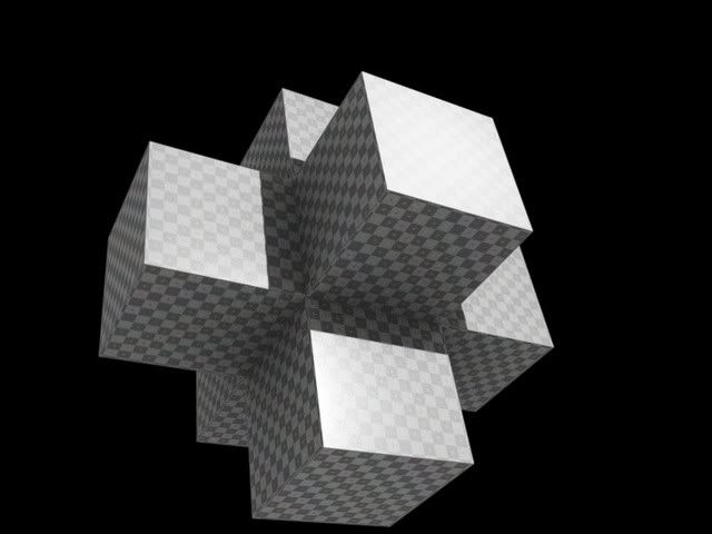
ok, maybe this picture can show the problem: the problem is, that the uv-map-node creates visible lines on the rendering (grey; in the picture left one can see them). these lines are the uv-seams from the unfolding (in my case: smart projection).
my questions: how can i avoid these visible lines on the rendering, when using the uv-map-node? isn’t that node useless, when it creates pictures with such lines?
http://img255.imageshack.us/my.php?image=screenshot2ka9.png
Greetz
S.
Simhar, at least some of the problem is due to that being purely the UVs - if you add in the natural colours and effects, it looks a lot better.
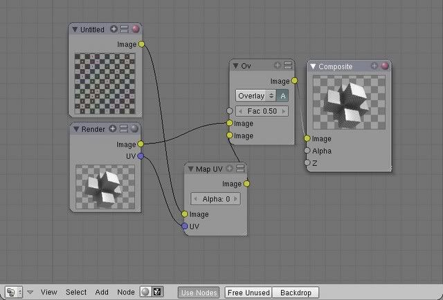
Here’s the node setup. Note the A (alpha) button turned on in the overlay node - this is vital!
 .
.
Well, you are getting closer to understanding. In your example, you are missing the mix node. The UV Map node puts out an alpha mask. the key word there being alpha. What happens when you overlay two images on top of one another without respecting their alpha channels? As long time readers will answer correctly, they multiply and give a halo effect at the edges. Search this forum for the words “strange halo”.
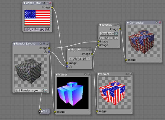
In my attachment, I have used the UV Map node correctly, by feeding into a mix node WITH THE premultiply ALPHA button (the Green A) enabled. This overlays the flag ontop of the grid, and no halo. Enjoy!
Yes! Indigomonkey beats the wikibot. (It’s a well-known fact that RogerWickes is in fact not human but a computer that automatically creates the wiki, thereafter churning out its information to all deserving users.  )
)
i must admit, i was amazed to see you beat me. congrats. But only by three minutes. And, wierd enough, we both gave exactly the same answer (which was also my first post). So i guess that means i know almost as much as you…or vice versa…hmmm…Would you like to take on ANY section of the wiki? The new Markers, perhaps? Updates needed to timeline and Ipo window sections.
wiki updated with second example. MY example. ha, indigo. now see, if you volunteered to be a wiki author, even for a little while, think of the power you would have.
Roger, I’d love to help in the wiki - I got me editing rights about a year ago, but didn’t really know where to start. Do the markers need doing within the next week or week and a half? I have absolutely LOADS of work to do in this period, but after then I should be able to help if I can. And I believe it’s a well-known fact that the best way to learn something is to teach it! 
EDIT: Oooh, you patriotic cad!
Hey PapaS,
I downloaded the example blend from the blender.org page. Nothing I do to that setup gets rid of the seams. I guess the difference is that I need to completely replace the surface texture of the object with new images.
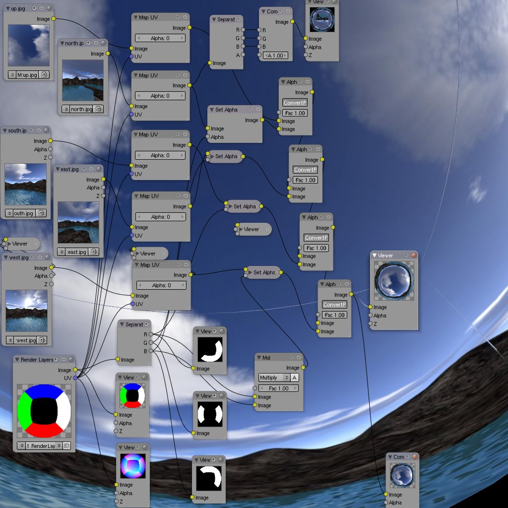
Here’s my unconventional fisheye conversion which I was hoping to do from 5 cameras (now shown as simple inputs.) Seams, glorious seams, how can I get rid of you?
I’m only posting this to make sure what I’m doing is outside the current map UV node’s abilities… But if it could work that would be super. I’m just not sure how.
I can email the blend if your curious.
anyone care to comment?
Hi! thx for the PM…, but I do not understand what you are trying to do, and what blend file did you download? If you post the blend to this thread, it would help. It looks like you are trying to construct a skybox with nodes…?? very createive…by…swapping the green or red or blue area of the rendered blob with an image, using the blob’s UV coordinates…??
Why not just texture the blob with the images directly?
So, I do see the seams alright…in the fisheye image…
We’re currently in production on a planetarium show using mostly XSI and Shake. I’ve thrown in some blender when I’m able and am also reconstructing the Shake composite in blender as an exercise in mine and blender’s abilities.
Anyway, this is an attempt at a quick-n-dirty domemaster. Currently, rendering a domemaster is expensive because the fish-eye like distortion requires raytracing. When I saw some things with UV map I thought maybe this could work (with better geometry of course) but the seams are getting in the way.
At the very least this could be used for previz.
In the blend it should become clear. UV is used to map the supplied images. RGB pass is used to control which image appears where. Eventually the 5 image inputs would be render-layers from a scene, but for now the skybox renders where quicker to throw in for the test.
.blend ~658k, right-click and save as
why not just, in 3D view, add a UV sphere, chop the bottom off, and seam it into a top and four sides, unwrap five times (each time a “side”), and then use texture channels to texture the sphere with those five pictures?
I will look at the nodes solution…but it seems to me a more basic issue of stitching together an image from different pieces… which to me is using the RGB key as a factor to the mix node…
Yeah, but that’s the obvious solution ;). In using nodes I saw the opportunity to set a scene up – say, a spiffy animation, then set up the node tree and click one button to render scene–>domemaster. All from one handy blend file. I love it!
To be honest, I haven’t explored your suggestion. Mainly because we’re pretty busy on the current shot… oh and most of the team uses XSI. Once I have the comp wrapped up on this shot I’d like to gather the assets (char, props, vehics) for previz’ing one of the other shots in blender. I explore other methods then.
Sweet! Thanks for looking.
The problem that you’re running into with the seams is this: UV pass is not just UV, it is UVA: the A being Alpha. The seams that you’re seeing are where the alpha channel is blending with the image below it (for some reason the seam edges do not properly multiply, instead the alpha edges of the seams appear to ADD together which kinda baffles me). If you don’t want this to happen then use an RGBA image to add character to your images in post, not to try and completely remap them.
Papa seemed to have gotten a kick out of a post I made about a flowered shirt a week or so ago. Well, this ain’t a flowered shirt but it’s close enough for gubbermint wurk. One flowered Suzanne coming right up. A Beautiful thing about Blender’s compositor is that you can render out one of these passes as an image sequence without having to re-render use the entire sequence (which may have cost a lot of time) and without having to use multilayer files, then recombine them as if they were a multipass file.
I would also like to express my sincere thanx to Adobe for helping Suzanne to Poke Smot via their custom shapes library in Photoshop!
The following leafs were added to Suzanne with the Map UV node. The rest of the texture is Tex Face UV mapped.
Edit:
Hmmm, after taking a closer look it’s not alpha that is the problem, it’s where the UVs get split at the seam. Have a look at the UV pass in a viewer node and you’ll see the problem. It does really strange things in the areas where the seams come together and are averaged due to aliasing. I really don’t see any reason why you need seams on the dome though. In the future just try to place any seams where they can’t be seen, otherwise you’ll be in for a nice little roto-puking session. Man, I hate that! I can hear the theme song now, “Who ya gonna call?..Dust - Busters!”