I’ve been having a few troubles lately, and figured it will be quicker to ask then figure it out myself.
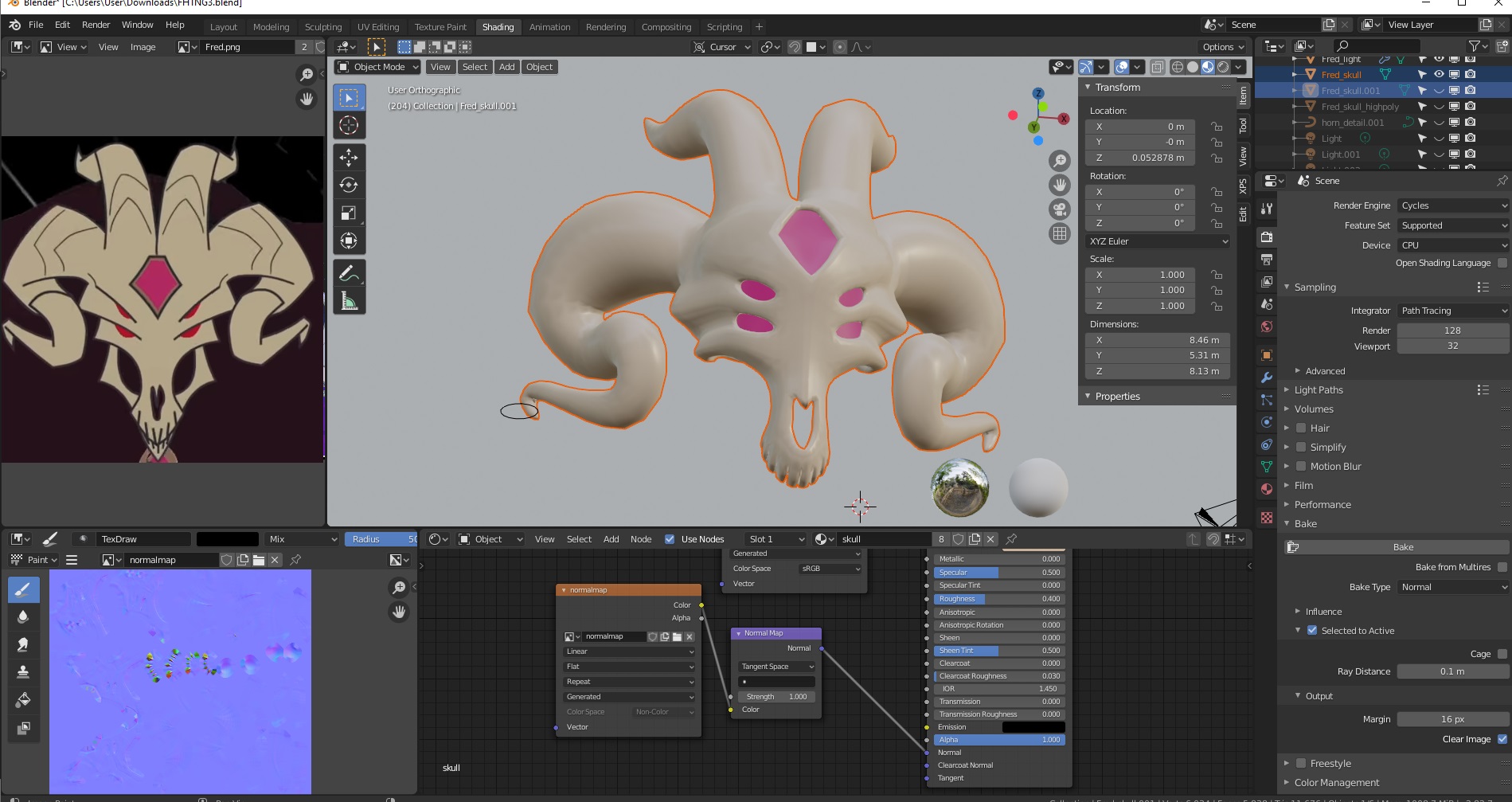
I’m trying to bake the normal maps from highpoly-to-lowpoly model, that I’ve seen done before, but for some reason it come off looking weird. I followed step by step instructions, so is there a step I’m missing or is it just the model? Adjusting the raytracing somehow just makes it worse; .1 is the best setting I found so far that causes the least amount of problems.
Here’s the source files. Maybe then it would be easier to specifically see what’s set up wrong. FHTNG_wip.blend (4.2 MB)
(Apply the subdivide on the highpoly.)
While I’m here, I have a side question: You notice how the horns kind of has creases in the concept art, what wold be the best/easiest way to apply something like that perfectly around? What I last tried to do was use 3d bezier curves, shrinkwrap them to the model, and then boolean it to make the creases, but obviously that causes its own problems and turn the mesh around it into a giant splintery mess, no matter how high or low poly I make it. Note that I was only going to use that as part of a bump or normal map, maybe it could be fixed by painting but it’s pointless if the entire normal map looks ugly anyway, right? Or maybe there’s an easier way that just hasn’t occurred to me, I want some tips on that too.
If you want to see more or better images I’ll provide it.
My skill level is somewhat intermediate, but it’s always confusing when you step into something you’ve never done something before.
EDIT: Baking emissions from a mesh solved my “project lines around a mesh” question. But if there’s anyone who has experience in normal maps, I would like to know what I’m doing wrong.
The problem is probably that your low poly intersects your high poly in some places. Adjusting ray distance helps in one place, but creates problems in another, right? Try using two different bakes with different ray distances, layer them in an image editing app, and then lasso + delete the bad bits from the top layer to reveal the bottom layer.
Since you’re baking high to low anyways, the best way to do it is with dynotopo sculpting.
If you want to do it with poly modelling, creases like this are done by creating three close edge loops and moving the verts of the central edge loop. (Frequently, these aren’t 3 full edge loops, but instead do a 3-to-1 join just past where it stops creasing.)
If your edge flow doesn’t support the direction of the crease you want, you should change the direction of your edge flow-- perhaps just locally to the crease. But if you don’t want to do that, you can create your lines with a knife or something and see how it works. (Basically, you’ll be creating some topology problems, but those don’t always matter that much.)
Not sure about the baking, but the creases could be done in several ways.
I wouldn’t recommend adjusting the topology to make them as you will probably just end up with a unnecessary mess. If you’re already baking from a high poly model why not just sculpt them there. If you’re having issues making them straight you can enable the stabilization in the stroke settings or use the “line” option instead of “space”.
If you don’t want to do that you could make a new texture and paint them on, again using stabilized stroke or line. You can use that texture as height input in the bump node and you’ll still be able to use your other normal map separately.
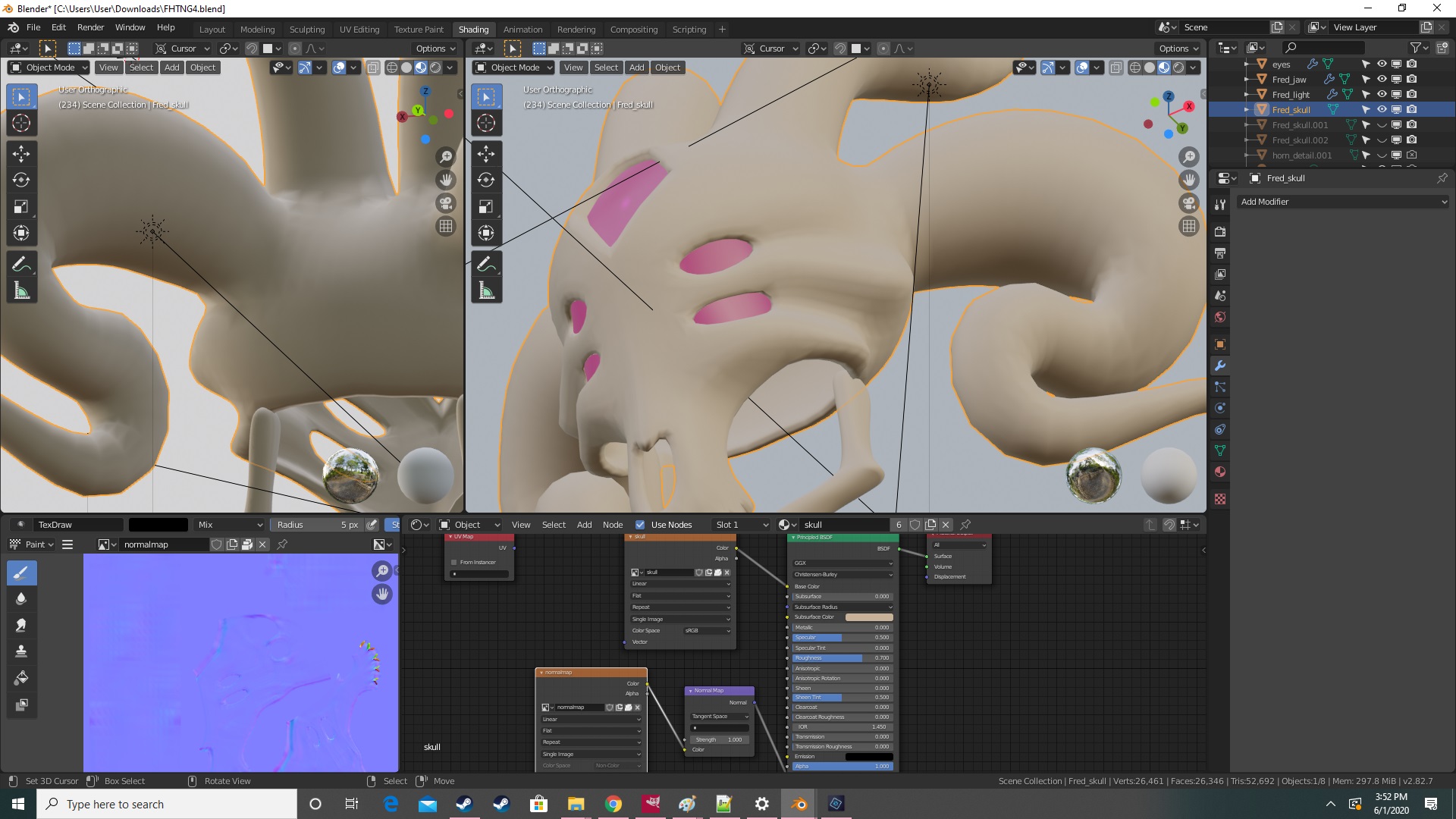
I still get the lines and checkerboard patterns, now matter how I set the ray tracing. Even when straigtening out and giving it more room, nothing.
Since it isn’t working I tried doing a cage like I saw in a few tutorials, but I get this.
Invalid cage object, the cage mesh must have the same number of faces as the active object
This must be uncommon because I can’t find a single fix that even talks about it. The number of vertices, edges and faces on the cage and low-poly are exactly the same. I followed several tutorials exactly so I have no idea what I’m specifically doing wrong. Here’s what the “lower poly” looks like btw.
Oh, and a bump map should work just fine (I don’t want them messing up the topology anyway), but simple doesn’t always mean easy.
Specifically, I was wondering if there were easier ways to get lines perfectly around the areas I want. (A black line around white is all I really need.) It isn’t that I’m too lazy to do it manually, it’s just that by doing it that way, they won’t come out even, which isn’t what I want; it isn’t like you can draw and rotate at the same time.
This is going to sound like a noob-level question: but there’s no way to project lines onto textures, is there? Like in a ‘thumbprint’ kind of way…?
A checkerboard on your image doesn’t necessarily mean a bad normal map. Look at the normal map when used on your low poly. Don’t look at the normal map image itself, that’s not going to much help you figure out if it’s right or not.
Try using “line” mode in sidebar/tool/brush settings/stroke, and disable normal falloff (/brush settings/falloff) and occlusion and backface culling (sidebar/options).
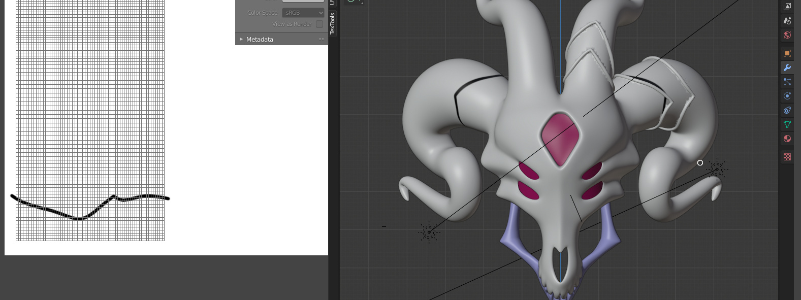
This is very useful for certain parts, thank you! Though sadly, it still doesn’t help with what I was looking for. (I didn’t mean a literal line…) Here’s the closest thing I can get so far:
Make the detail as a nurbcurve, and booleon or bevel it to a separate model, then use that one’s uv to draw a perfect line across where I wanted it to go and use it as the bump for the creases. I kind of suck at doing that in Blender so I could bring it into gimp and photoshop to draw the line. That works, but just for the future, I was wondering if it was possible to just kind of silhouette one object onto another as a texture. There’s “UV projecting” but I haven’t gotten into detail about that yet.
Here’s how it looks on the model, (still looks like cr*p.)
For clarity, I don’t really have a lot extra detail on the high poly; my intention was just to use a normal map to make this and all the other models I’m making appear smoother. (They don’t necessarily even need it, but I thought if there was a way to make them look more high-poly in other programs, I’ll use the extra map.) For that context, am I even using the map correctly in the first place? (This isn’t my first time working with normal maps, but it is my first time making my own, and using it on an entire model.)
Well, I mean, once again, what you should be doing is dynosculpting it so that it shows up in your normal bake (forgetting about the problems there, for the moment.)
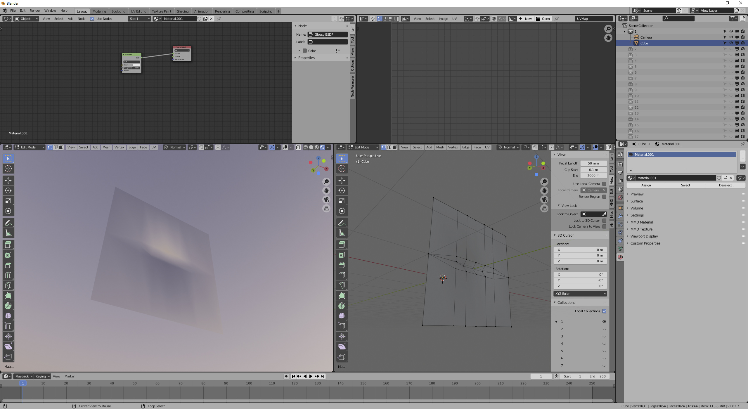
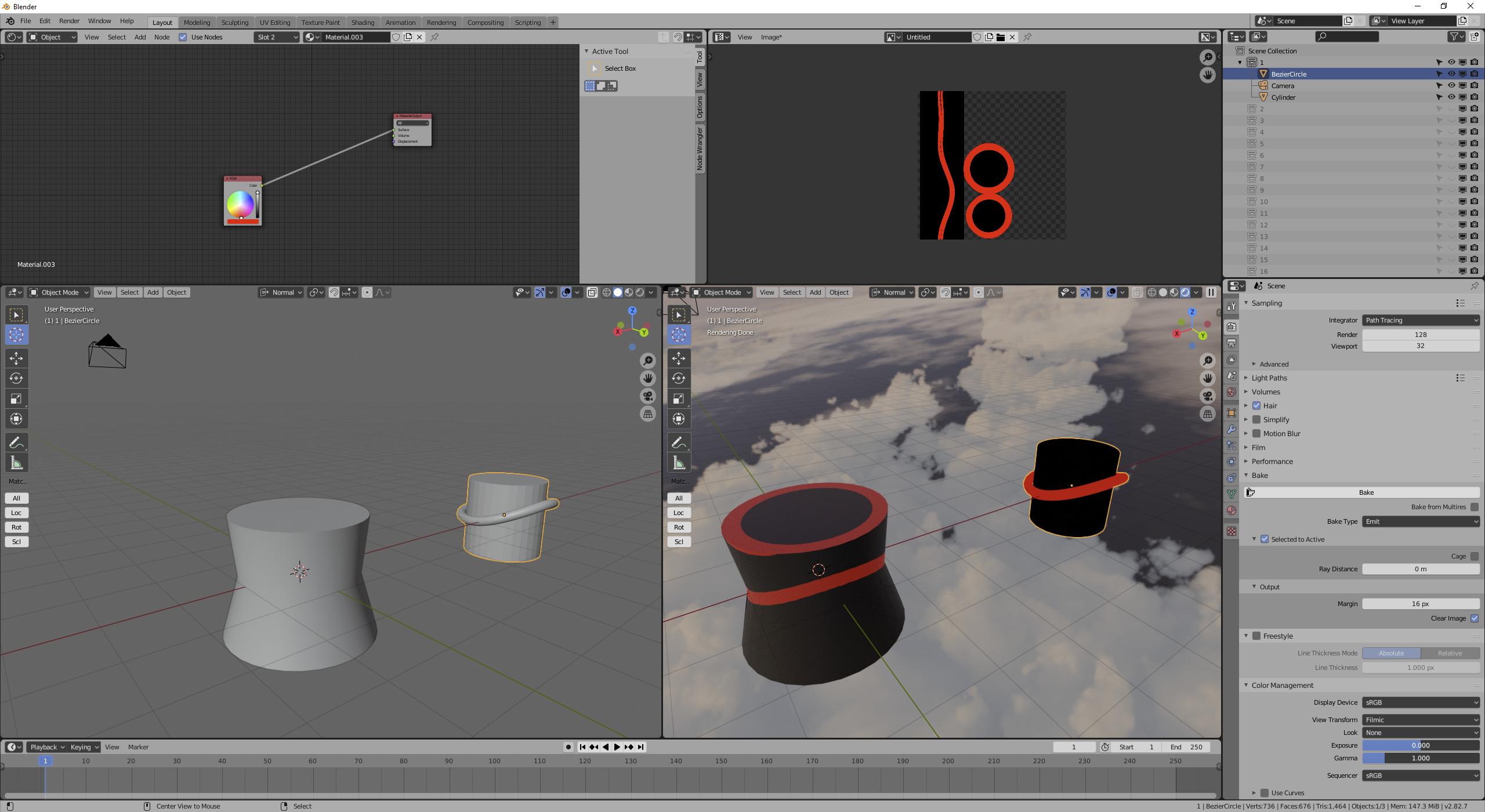
But if you want to use a mesh to draw a line on a different mesh, you can. It’s very similar to baking selected-to-active (high-to-low) normals, except instead of baking normals, you’re baking something else:
I baked emission from the mesh + materials on the right, to the mesh on the left. Of course, they were right on top of each other-- I moved the source over after baking so you could see.
What I did, isn’t very good. Selected to active baking is not something I have a lot of experience with. But figuring out how to get what you want with this is actually a good way to learn how to get what you want with normal maps, because it’s so much more immediately visible how the rays are acting. (Notice how my cylinder’s top face picked up the emission of the mesh underneath? If we were doing normals, that would have happened too.)
Should be said, there are other stroke methods besides “line”-- there’s a curve stroke, too. Although that’s really a 2D projection of a curve still.
Yeah, it doesn’t look good. I couldn’t tell you what’s happening without seeing a file. Maybe not even then (like I said, this isn’t really something I have a lot of experience with.)
However, yes, it does look like you’re using the normal map correctly. The only thing I’d recommend is to explicitly choose the UV map you’re using for the normal map on the normal map node’s tangent field (the empty text box). Still, that’s not going to break anything until you start dealing with multiple UV maps.
The emission baking is just the kind of thing I’m looking for, I just didn’t know how to do it until now thanks!
As for the normal map, just in case, I’ll provide the file in the OP, fee of most clutter, for anyone to have a look at it. A shot in the dark, I know, but just maybe you or someone else can see what’s going wrong that I can’t.
If there’s any other suggestions or tips too that are relevant I would appreciate it, everything is still a wip. Though just to be clear, I’m asking others on HOW to fix it, not requesting someone else to fix it FOR me. (Teach a man to fish etc.)
A cage is made from the low poly, by duplicating it, so it has exactly the same amount of faces. If the number of face is different, you get this error message.
After you can tune your cage in edit mode, or in scult mode (without dyntopo ofc) to have it “swallow” the high poly. A good tips for that is having the hi poly with a viewport color (let’s say red) and the cage another color, so you can see were the cage need to be tuned up.
Now, around the teeth, the geometry is really tight and it’s gonna take some time/fiddling to get correct and even then, you might have to cheat with correcting the normal map manually.
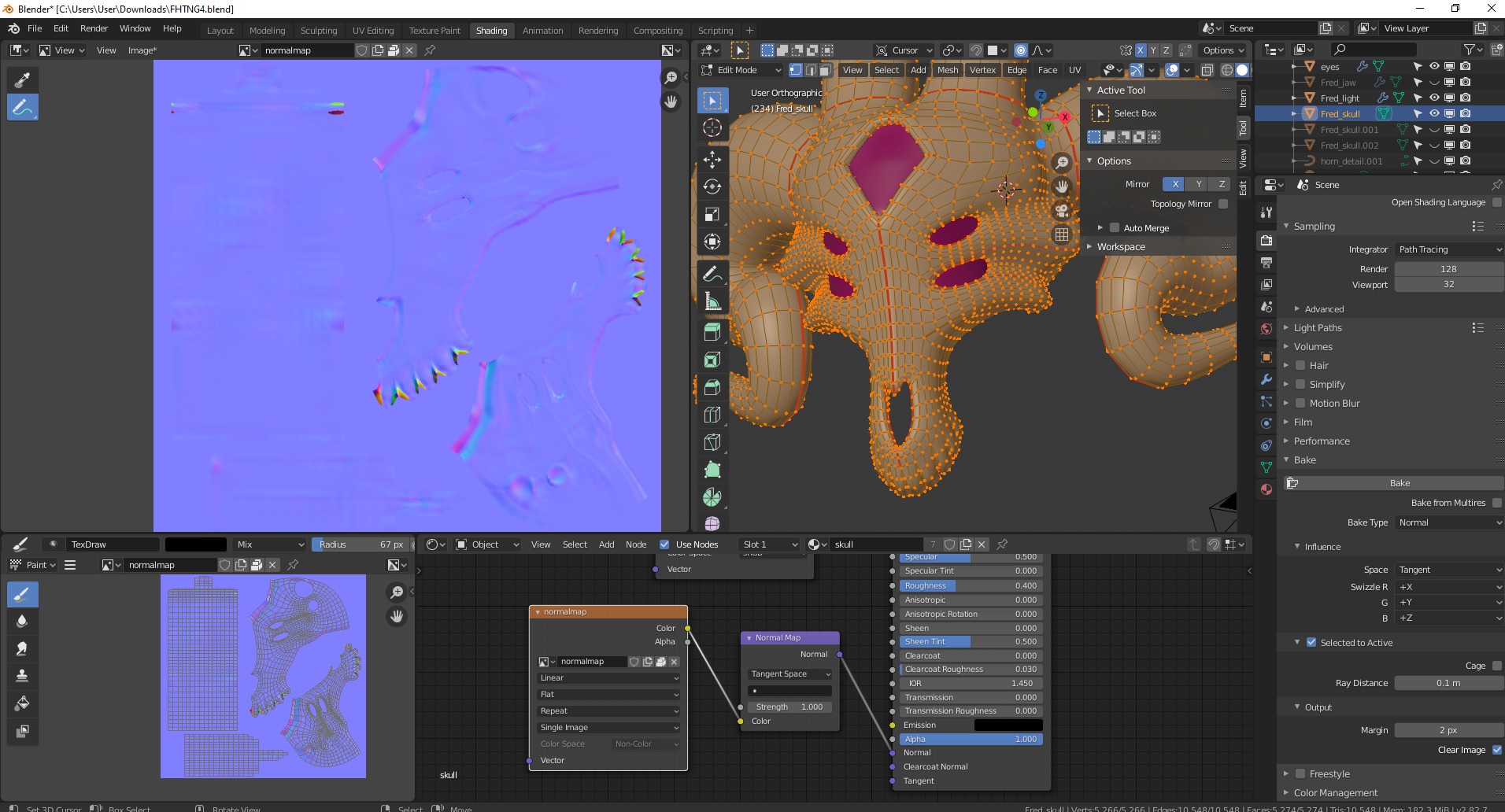
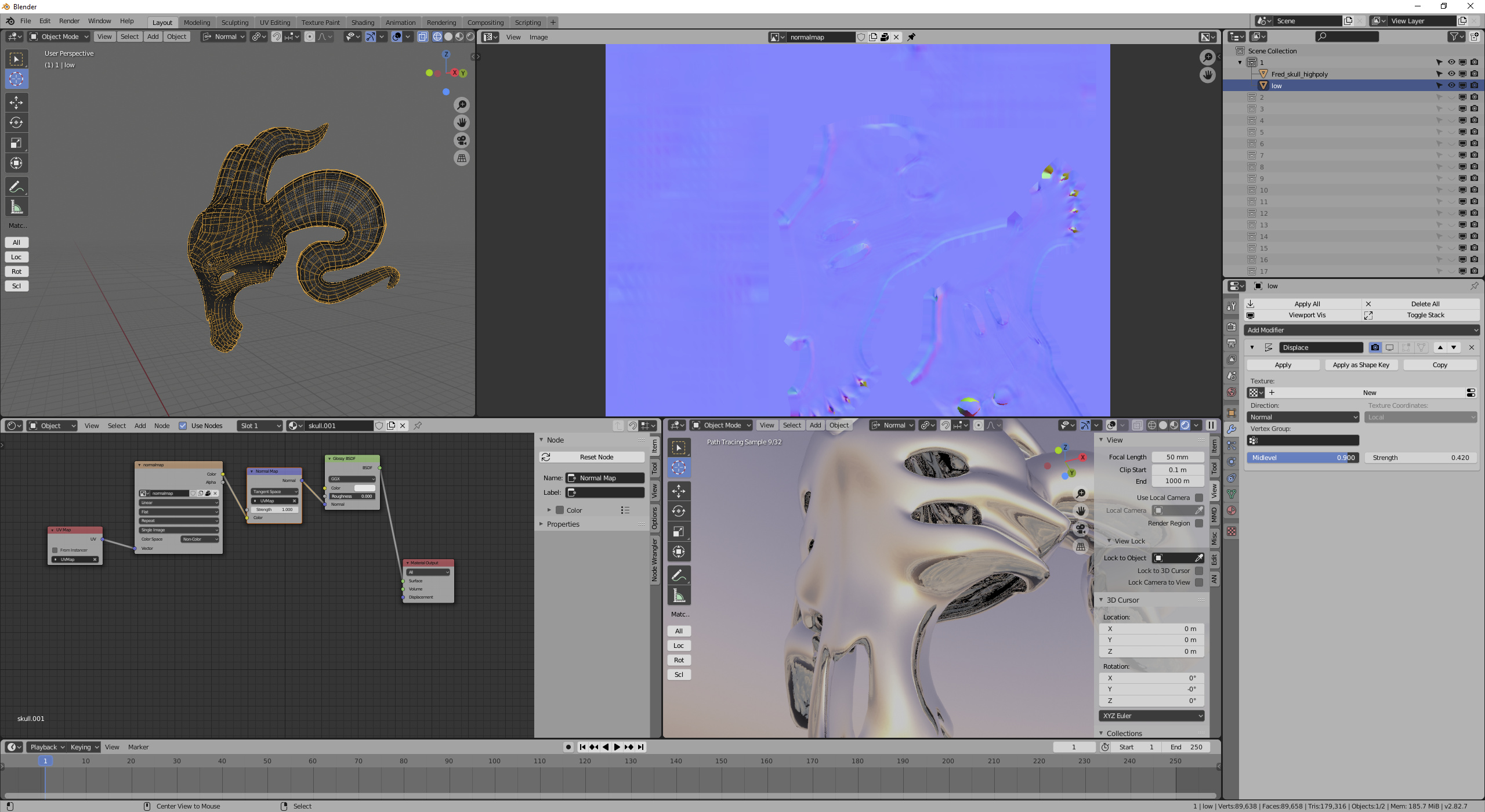
So first, I kept getting weird errors on trying to bake. So I copied your objects to a different file and deleted all materials from the high poly. Notice that the high poly was also assigned the normal map, which creates a cyclic dependency-- it thinks it needs to know what the normal map is to find out the normals for the high in order to write the normal map. Can’t read from and write to a single image on a bake. If you’re baking normals, your high poly doesn’t need a material.
After that, I figured I could probably avoid your intersection problems. Ray depth is one way to do this, but hard to visualize the correct value, so I just gave the low poly a displace modifier and then tuned it to enclose the high poly. (Displacing evenly along normals doesn’t change the normals, it only changes the positions. That makes even displacement a safe thing to do for normal map bakes.)
I also turned off autosmooth on both meshes and set them to smooth shading. Not sure if that can cause a problem, but in my imagination it could
After that, I baked. Didn’t see any grid artifacts in the render (remember, the normal map image can be griddy even if the render is right.) Disabled the displacement and checked with 0 roughness glossy. Looks good to me?
Unfortunately, I didn’t find that video very useful, because he was doing a cage on something that didn’t actually need a cage. (Ray distance, or what I was doing with displacement, would be fine.) In the few places where he didn’t just move the cage verts along normals, he didn’t zoom in or spend any time talking about how that affected things.
What direction does it shoot? From the cage position, along cage normals? Or from the cage position, but the low poly normals? How does it map from cage to low poly-- barycentric coords? Like UV interpolation?
I suppose I could figure this kind of stuff out with some experimentation. They’re the kind of details that I need to feel comfortable with a technique, but the kind of details that Blender tutorials don’t get into (one of the reasons I don’t watch a lot of tutorial videos.)
A cage mesh is something I tried to do earlier after looking at that tutorial, but I get the invalid cage object error even though both have exactly the same amount of faces. (Do they have to not overlap and/or does the cage have to cover everything completely to get it to even try?)
Don’t think(or at least recall) I’ve seen that error myself. But I’d say that ideally you wouldn’t want it to overlap.
Did you duplicate and just use shrink/flatten operator to inflate the low poly mesh?
That’s be the best since I’m pretty sure the cage has to be identical as in the vertex indices need to match up between the low poly and the cage. TL;DR: its safe to move the vertices around but don’t change the topology.