Normal map problem with Magic UV Flip/rotate - Blender 2.79

Hello. For a week i’m fighting with this, i maybe pinpointed how my problem is created, but i have no knowledge to understand it and fix it.

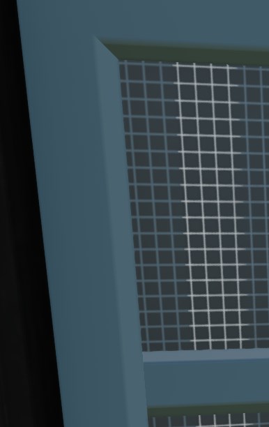
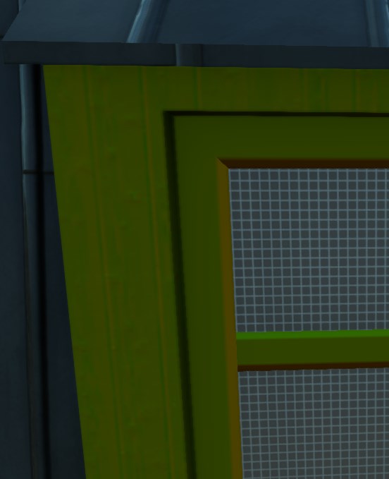
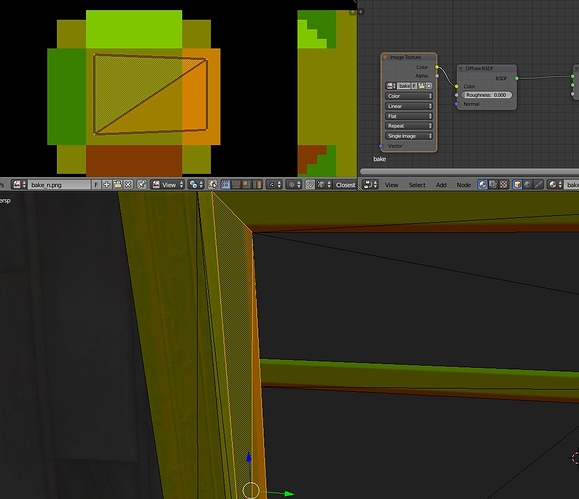
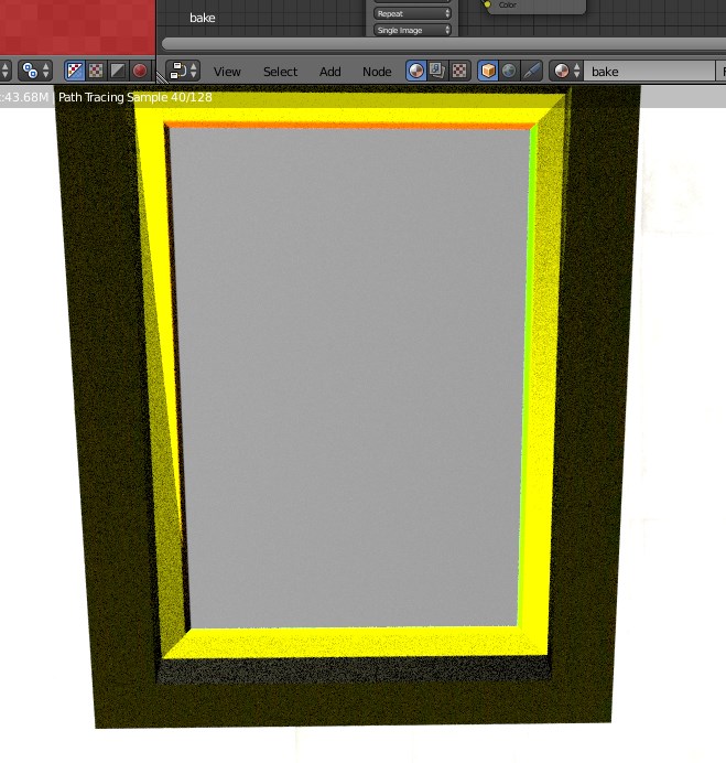
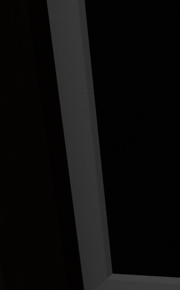
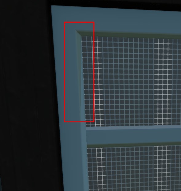
I’m doing simple false edge at flat window frame with normal map. Next images are for broken one.

  1. In-game look with basic texture:
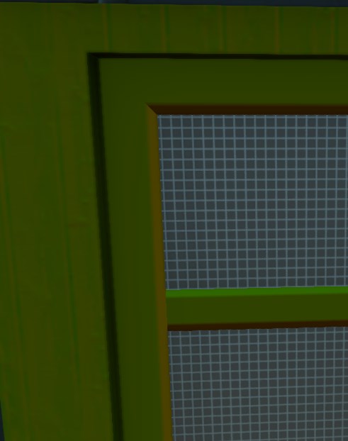
  2. In-game look when i use normal map as a texture:
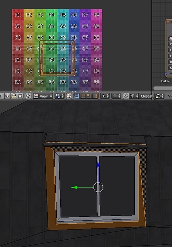
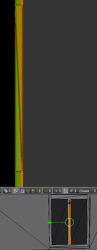
  3. Blender view of faulty area:

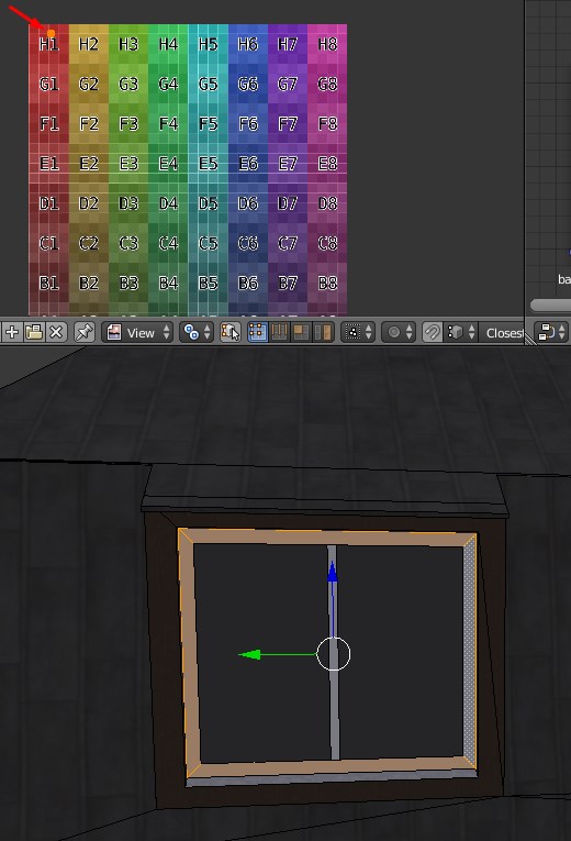
For comparison here are same images for frame without normal issue:

I was already solving somehow similar issue at this forum (https://blenderartists.org/t/normal-map-render-problem/1227271) I learnt there that texture pixels are rotated by normal map and only then texture is applied to polygon. From look of my current problem i would say that somehow same thing happens here, that my UV is rotated before applying to polygon. But i have no idea when and how that happens.

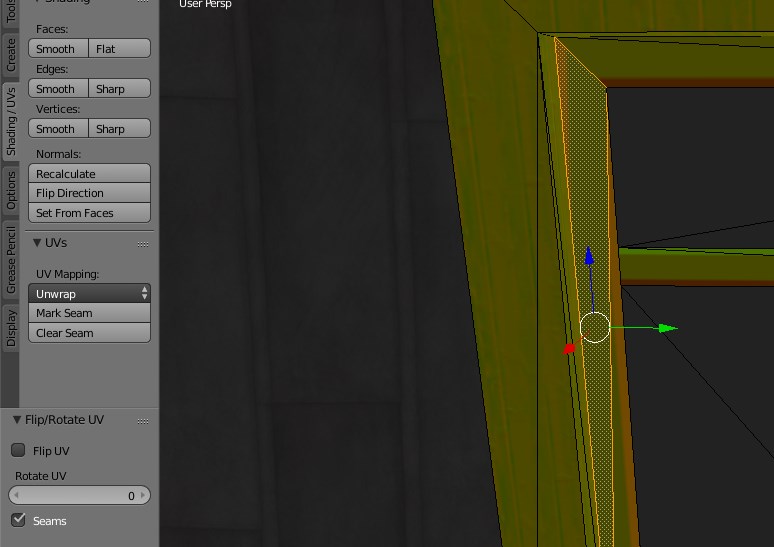
My workflow is following: i UV map all edges at one window. Then i use UV magic add-on to copy UV to other windows. When i do that, very often UV doesn’t match and i use UV magic Flip/Rotate to fix it. Like at following example:


There i copied my ok edge from previous example to wrong edge from previous. I use normal map as a texture to see if UV is fitting or its rotated. Here in this case i used Flip/Rotate with following settings to get look i wanted:
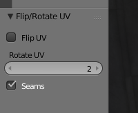
image
In this case edge is really fixed, and it shows properly in-game. Problem is when i do this at mass scale, copy one window to like 10 others, 50% of edges are correct, 50% are wrong… I use this tool a lot, it speed things up a lot, so i really need to crack this…

Sorry if my description is too long, or if its missing something, i will be here tomorrow to add any more information if needed.
Yes, if you feel like you have to flip or rotate UV some of the frames, then any tangent space normal maps will no longer be accurate.

The reason that you feel the need to flip or rotate the UV is because your geometry has been altered. Instead of altering the UV, you could alter the geometry (select all, rotate 180 degrees or scale -1 in local x followed by recalculate normals.)

You could do some correction in the shader-- maybe a lookup on a tiny texture that indicates flip/rotate-- but that strikes me as a little bit silly. Otherwise, you’d have to create new, separate normal maps for any of the objects where you flip or rotate the UV. Which would probably also mean, UV occupying a different part of the texture.

Since these are (presumably) non-deforming bits of geometry, you could also consider the use of object-space normal maps, which don’t care about UV manipulations.

Also: I’m not sure that it is, but if that green color texture is supposed to be a tangent space normal map, then something is seriously wrong with the normal map. I say this because I looked at your other thread, where the image you’re showing is definitely not a tangent space normal map (or if it is, is completely wrong.)

It should be perfectly ok tangent normal map, only with blue channel set to zero.

Thing is i UV mapped / copied / flipped those window frames before triangling my mesh. So i don’t understand how is it possible that only some triangles are wrong. Before i had that one side of frame made out of 5 triangles, and only 1! had normal issues. Now i simplified it to two triangles, and looks like triangles are rotated to each other. I really don’t know how should i alter geometry of one triangle only, when those triangles creates one face at quads…

Oh, okay. I’m not familiar with how normal maps look without a blue channel, so that makes sense.

You’re right, if it’s identical geometry, and identical UV maps, there should not be any per-triangle issues with the normals, only possibly per-object (per-manifold-mesh) issues. The issues I was talking about wouldn’t show up on a per-triangle basis.

The exception to this would be if the meshes got triangulated in different fashions, so that they’re not really identical geometry.

I’d have to see a file (with packed normal map image) to tell you more.

Here is the file, i hope i packed texture and normal images corectly.
hipoly_mirror.blend (4.3 MB)

I don’t have any setup in blender to use normals, no proper lightning, i’m sorry. It would take me quite some time to do that, becouse normally i just export model straight to game and look how it renders there.

Almost vertical window frame is broken there with few exceptions. Every upper window at long side is broken completely, so you can look there for example.

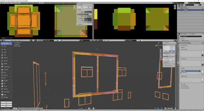
Okay, so let’s just look at this with a color grid, and look at the UVs.

So first, look at the UV map. Notice all those overlapping faces? They’re not congruent faces. These frames don’t share topology, which means that they can’t really share a tangent space UV map. All of those various triangulations are going to cause problems in reading the tangent. (More, the vast majority of your faces are actually ngons, which are going to be triangulated differently depending on where you’re rendering-- a normal map baked in Blender is not necessarily going to be appropriate once your engine triangulates those faces in its own way. This may be why you were seeing triangle-specific errors.)

I also suspect-- not sure-- that the fact that some of these are mirrored is going to cause problems. Look at some of the text is backwards.

If you want to use the same texture space for these, you’re going to have to start over on a lot of this stuff. Make a single frame. Triangulate it, possibly with an applied triangulate modifier. Create an appropriate UV map for it. Bake a normal map for it. Then duplicate that object and place it wherever you need a frame. Don’t touch the UV or the topology after you’ve baked the normal map. If they require different topology or different UV, they need to occupy a different part of the texture.

I don’t see any Ngon, all frame faces are made out of 4 vertices. ( well i found one ngon i missed when i was fixing those faces, but thats probably all).
EDIT: Ok, i can finally see why your screen is so different. That faces you selected are not window frames, it is a wood wall. I haven’t bothered to fix those with Flip/Rotate, becouse with even flipped normals you can’t see the difference in-game.
But i have issue with my false edge between frame and glass, i marked it at my screens… I guess i should have send project version with splitt materials, sorry.

Anyway if i use that color grind and check my frames, it looks ok. Tbh i don’t know what difference between using color grid image and my normal image. At both i can see unwrap is OK. And at none i can see if that unwrap is rotated to polygon afterwards.
Probably i’m completele missing something…

Yes, i used mirror, i modelled only half of that house. No idea what to do with that, mirroring UV is completely useless for bakes.

If that wasn’t the part I was supposed to be looking at, I have no idea what was. That’s the part of your mesh that’s mapped to the part of the image you’re showing above.

You looked at this:

And this is where my issue is:

Actually, removing the blue channel of a normal map totally ruins it!
Why have you done that?
If I recreate the Blue channel, I get good normals and a nice looking house.

Game i model for use Blue channel for glossiness. Anyway why would blue channel ruin my X,Y axis??

I’m going to setup nodes to show normals at Blender render, so we can all talk about same. Never done that, so give me few mins :slight_smile: .

Probably your game engine does something similar to what i’ve posted above, but in Blender you have to do it by hand.
Here’s the difference of the Normal Map output with and without the blue channel…

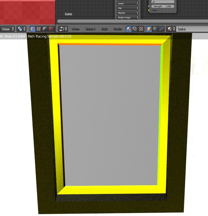
Ok, here is what happens directly at Blender.
Point light source, i used my normal map both as texture and as a normal.
Quads:

And when i triangle it, left edge breaks? or whatever it is :

So question is, why after triangulation one of those triangles seems to be rotated, while second stays at place?

Please note i UV map those faces to very few pixels…can that cause any issues?

EDIT: ok, seems that without blue channel at normal this post is kidna useless :D.

Ah i see. Ok, i added blue channel to my normal, now at every other material normals looks nice, but my window frame have absolutely no edges. I’m going to play with lightning, maybe i can get some results with better lightning.
OK, i had to remove lot of light to make edges visisble.
Before triangulation:

After triangulation:

Because of the distortion of your quads, when you triangulate them, you also distort the tangent vector…
Fixing this is not an easy task, as you might need to reproject your uvmap and rebuild your normal maps to the triangulated tangents.

1 Like

So you are saying that problem is i unwrap very long tiny face to square shape? I thought about that, but didn’t understand why that would become problem only after triangulation.
Ok, at one model i don’t have any more bakes at image, so in few hours i will remake it for test, i will create it as a tiny frame at image border, that should be a good shape.

The faces aren’t just very long, they’re also trapezoidal, yet mapped to squares. They’re highly distorted. You can see the effects of triangulating faces that have been mapped like this pretty easily in Blender: give it a color grid, triangulate the face, inspect; undo, triangulate the other way, inspect.

When I look at the part of the mesh you’re indicating, it has the same problems I mentioned before, in that the various topologies don’t match up, various frames represent completely different meshes, faces are reversed (inspecting with a color grid), etc. There aren’t any ngons, but nothing is triangulated, and the UV map is heavily distorted.

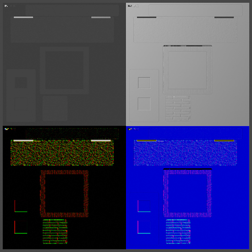
But there’s also a new problem, which is that your normal map just doesn’t make any sense. Possibly due to pixellation, and trying to map your frames on to too small a part of your normal map. Here’s a close up:

So look at this big flat fields of color-- and then look at the UV coordinates, sprinkled loosely across that field. Is that going to make any sense?

(Below that is a color map using a re-scaled UV map so I could see what was going on. You can see the way that mapping a trapezoid to square UV is a bad idea, and you can see the backwards, mirrored UVs.)

For the normals I’m seeing here, I wouldn’t even be using a normal map-- use custom normals instead, if that’s what you want. You’ll have fewer errors, and your image doesn’t have the resolution here to support what you want.

However, if you really want a normal map, the same advice that I gave earlier applies-- UV map, triangulate, bake, duplicate objects-- except, here, you’re trying to use about four different frames, so even with reuse of texture, you still want this section of the map to be four different sections.

So i tried so UV map edges again without non uniform scale. But i still tried use very few pixels, and seems it won’t work.
image
(fake edge is 3 pixels wide, flat area is 9 pixels wide)
Always tip of that triangle is displayed wrong. I guess distortion will happen always, unless i map it to much larger area, and i can’t really afford that. I have one image to bake everything to and this detail is too small to be worthy.

Only thing i don’t understand is why it happens only at vertical edges.


All my horizontal edges are maped more or less in same way like horizontal, but its always displayed correctly.
And also partions are always correct, although i would think its almost same as vertical edge:

Anyway this become too big pain in the ass. I thought i will learn something, but in the end i’m more and more confused. So i will drop this detail out of my model and just hope i never encounter it again. Just stay away from any small normals details i guess…
I guess next time i will model one window frame only, and then duplicate it to use it at all other windows. Ofc i would have to scale it for different windows, but topology should remain same and i can copy/paste UV then without any issues, right? And then i simply bake real normal when i model that edge, and it should work i hope. (well god knows what mirror modifer willl do to that, but i will have to make it and see i guess :frowning: )

I don’t know what custom normals are. From quick study i would guess you can change face normal without changing its actual geometry… but why not change that geometry instead. And i don’t understand how would you fake edge at half face while leaving other half of the face straight. But i might missunderstood what custom normal is.