Hello everyone - I have a question - it is necessary to make a sphere tessellation to generate a future planet in UPBGE v 2.0.5 and I do not know what to start from - as far as I know, all the main examples boil down to an endless landscape, which consists of sets of tiles that are substituted when the player reaches the edge of the current tile, but I did not find information about the generation of a subdivided sphere in the engine - my questions: 1. Is it possible to use the bpy module in conjunction with the python game engine for these purposes? if so, where can I find information about this API? tutorials? 2.Where can I find information about the division of the grid in the vicinity of the player’s camera - I am interested in the division of the grid according to the coordinates of the UV scan - for its further displacement 3. Is it possible to do this without GLSL shaders purely on python? I would appreciate any information, I know the information on how to get a list of the vertices of an object, their positions and movements
‘mesh = own.meshes[0]
for v in range(mesh.getVertexArrayLength(0)):
vert = mesh.getVertex(0, v)
pos = vert.getXYZ()’ - I need information on how to divide the grid into, say, 10 x 10 squares to have dimensions of 100 x 100 and further
or will I have to make a projection for these purposes? - by dragging the vertices from the back of the mesh and arranging the mesh with them closer to the camera to get a high-poly surface and only then produce surface offsets? - I will be grateful for any hints or ideas
Well, I looked through my question and looked for information about generating landscapes in bge/upbge 2.79 via python - you can do this by changing the position of the mesh vertexes and recalculating the mesh physics. I found a very interesting example that the user sdfgeoff did, the example works well and generates a landscape from height maps, but does it according to the world coordinate Z+ and it shifts the surfaces of the spheres in the same way - like a rag - and when it is shifted from the center of the coordinates of the scene, it projects elevation maps onto the object differently - I would like to know if it is possible to redo it to shift the surface of the sphere in order to be able to shift the vertexes according to the coordinates of the vertex normals, as is done by the script
``
from bge import logic as GL
import random
def init(cont):
own = cont.owner
redarw_land(cont)
def redarw_land(cont):
own = cont.owner

# get the 1st mesh
mesh = own.meshes[0]
for v in range(mesh.getVertexArrayLength(0)):
    vert = mesh.getVertex(0, v)
    pos = vert.getXYZ()
    norm = vert.normal * random.triangular(0.0, 0.015)

    vert.XYZ = (vert.x * norm.x, vert.y * norm.y, vert.z *norm.z)
``
Terrain.zip (126.2 KB)
this is an example of a tile generation file made by the sdfgeoff user
Well, again, I’ll rephrase the question since I found a solution for the sphere, I was able to shift it in the game engine - and the last question remains, I used the built-in math - noise textures data module, but maybe there is a way to use texture maps of heights instead of the maps available in the noise mathematics module? is it possible to somehow get pixel values and match them with UV to offset the surface?

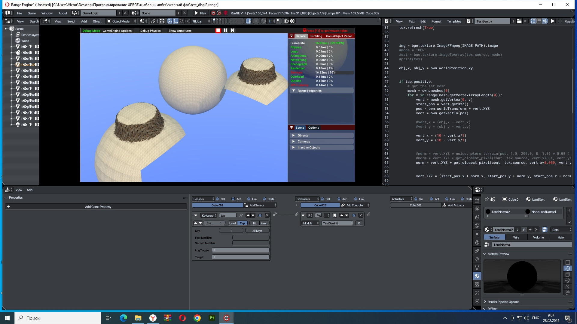
my solution boils down to using the displacement of the sphere vertices and the data for the displacement is taken from norm= vert.XYZ * noise.hetero_terrain(pos, 1.0, 200.0, 8, 1.0)*0.05 which generates a procedural texture and makes an offset based on it, but I need to get and embed elevation maps - for example, textures of the heights of planets with craters or erosion mountains, I’m already thinking about how to try to extract data from a material id or image
I’m removing my question - I solved it using the example of Sdfgeoff from the blenderartist community - now you can use custom elevation maps for regions to generate a surface, the problem of the example was with setting the position of the UV map - I took a tenth of the texture size, subtracted the position of the vertex of the corresponding coordinate and divided it by one and the offset stood in the center of the map scan


I’ll just leave it here.
owh…I should replied this in here.
This is the best sample to generate mesh+heightmap which is over scripted.
But I just needed the same mesh that doesnt work as instances that overwritten the logic.
So what I want is whenever the terrain mesh is added in different location as instances the displace script follow the uv global coords but still using the same mesh.
In the other words a working script of displace modifier in BGE.
The uv coords just works well perhaps by default as Global UV but the mesh is the new one.
you can move the center of the grid according to the XY coordinates for the player if he goes far from the center by simply getting the distance dist = gride.GetDistanceTo(player) if dist>=15.000: new_pos= player.worldPosition gride.worldPosition = [new_pos[0], new_pos[1], 0.0] and then only the problem remains mesh rearrangements that can also be solved - either use a grid with a surface subdivision within 50-60 thousand polygons, then the landscape is rebuilt quickly, or use two grids - the first is a decorator that creates a beautiful landscape, the second grid is not a visible object for collisions with a simplified grid structure in any case, you can find a solution even for a dynamically tunable grid
And in this topic, I asked a question about the possibility of tessellation of grids in the blender game engine - but I had to look for a solution on my own and it comes down to using prepared grids since I did not find information on how to make tessellation in the game ![]()
I was using the code from Terrain.zip sample partially, just for heightmap vector not anything elses.
My methode is like quad cell generator, plus heightmap.
This is my working progress on heightmap methode, sadly standalone player can’t register the modifier ![]()

and this is the code from terrain.zip as you can see, the mesh obj data overwriten the script but works fine if the mesh data is new (not linked/same user)
the 1st picture is same/multi user

the second picture is the new mesh data on 2nd terrain, script work fine

if you use any modifiers for the terrain and then try to generate the height with the code, access to the vertices will be blocked by modifiers - to avoid this, disable the modifiers from the active ones (you don’t have to delete them - just disable them) then the height script will iterate over the vertices and rebuild them, if you want to use height maps as the offset modifier will do, you must either bake the animation keys and then reproduce this animation (which will be expensive in terms of file size of about 185 MB per animation saved in a blend file) or use baking height maps from the resulting landscapes and then use these height maps to offset during generation (this is a very cheap method of height maps even in resolutions from 2k to 4k weigh a few few MB)
The TEST files doesn’t have modifier just python script, If both is used it will crash.
And Im not looking for heightmap bake to mesh/shapekey.
I just need multi user mesh to be works like desplace modifier. But the mesh data on 2nd terrain just overwriten the script following the 1st terrain mesh because its same/multiuser, so is there any script that may prevent this…so Im figure it out on the object ID index now.
now I think I understand what you mean - in order to use this script on different parts of landscapes, your own material must be created for each landscape object, since the script works as follows - it replaces the texture of the current object through the material, which then reads from the image buffer and displaces the surface - if you have 4 sections of the landscape or more for each one needs to be assigned its own material so that the script shifts the surface without repetition, in order to use different materials, create a property with the name of the material for the object and instead of the name of the material MA + “landscape” substitute the property of the object MA + str(own[‘mat_name’]) then using one script you can assign different terrain to different parts of the landscape, in the same way you can assign different maps for landscapes through properties - own[‘texture_name’] +“.jpg” when you call texture loading from a folder, this is useful because it will allow you to change the texture names to create a completely new location from the same objects that you have in the scene - the only thing you will have to do is assemble a shader on the nodes to texture the landscape because the first texture slot is occupied by the height texture - if I misunderstood you again, let me know - or specify in more detail what you want, since I use a translator and it does not always accurately translate technical terms
Actually I already done the terrain by using 4 different mesh, and its so perfect what i want it to be, even though its not fixing the overwrite issues, but perhaps nextime due to complexity on the script.
I solve it in classic way on my terrain generator and has great chances to be infinite if I finish it on grid methodes by using kdtree functions but its takes time.
I will upload the videos … soon ![]()
ok - i waiting
Sorry for late response, but I will make the videos later…
In my last questions that should be in this topic.
I think the Heightmap methode was incomplete and should be better improve even tough its just a minor problems.
The Normal map should be works, but after I check it was almost imposible the changing mesh to be set to the world on its normal vertex, and kept the facing data as flat or facing z up.
So there is no solution on post-render, and the only things that can set properly is in Editing Mode.
After I play old skyrim game, I notice it was the same issues, that the ground mesh which is using heightmap as well, was no vertex normal at all, and this is one factor that increase performance on their creation engine.
The shadow is using local light (sun) and that is the same thing that I just working on.
I will upload the test videos soon…including the infinite terrain using kd tree.
For now I continue my project which is takes a lot of time…and effort, hopefully my health getting better as well…
I don’t have any problems with the shadows…yet ![]() and I was wrong completely about the script that should be work properly, and find another issues on the heightmap script which is hidden all along.
and I was wrong completely about the script that should be work properly, and find another issues on the heightmap script which is hidden all along.
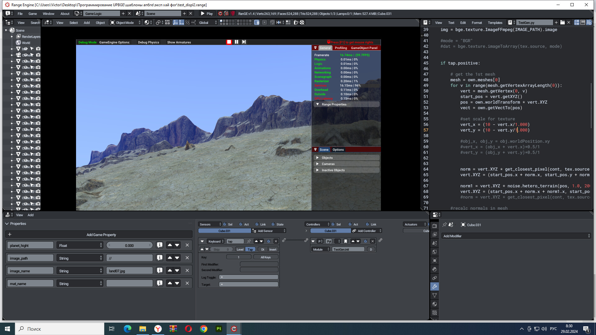
The Script on the z vector mapping is not accurate, because the sample is using small resolution of heightmap texture so its looks very accurate but not on larger resolutions.
So my heighmap size is bigger about 2048 pixel then I check the script on the center of the map is not match the height, but the size and x/y wrap is perfect.
This is the comparisson between the displace modifier and the scripted heightmap.
Edge of the map (left side of 3d preview):

Center of the Map:

The issues is the z vector around the edge of the map is more values than in the middle, I assume the z tangent vector is not linear.
How can I fix this small issues just coming again and again. ![]()
So I use the heightmap script partially based on Terrain.zip then use delay sensor to activate it on the flat mesh below:
import bge
import math
import mathutils

SCALAR = 0.001224
VERT_SCALAR = 0.42
IMAGE_PATH = bge.logic.expandPath('//youreheightmap.png')

#RECALC_NORMALS = False
RECALC_PHYSICS = True

PLAYER = 'Player'

def init(cont):
    #Load Heightmap
    obj = cont.owner
    mat_id = bge.texture.materialID(obj, "MA" + "yourematerial")
    tex = bge.texture.Texture(obj, mat_id)
    tex.source = bge.texture.ImageFFmpeg(IMAGE_PATH)

    cont.owner['tex'] = tex
    tex.refresh(True)

    #Do the first draw of the land all in one frame
    redraw_land(cont)
    recalc_physics(cont)
    #recalc_normals(cont)

    cont.script = __name__+'redraw_land'

def recalc_physics(cont):
    if RECALC_PHYSICS != False:
        cont.owner.reinstancePhysicsMesh(cont.owner, cont.owner.meshes[0])

# Face normal not working after post-render in most game engine -_-
#def recalc_normals(cont):
#    if RECALC_NORMALS != True:
#        return
#    mesh = cont.owner.meshes[0]
#    mat_id = bge.texture.materialID(cont.owner, "MA" + "LandNormal")
#    for poly_id in range(mesh.numPolygons):
#        poly = mesh.getPolygon(poly_id)
#        v1 = mesh.getVertex(mat_id, poly.v1)
#        v2 = mesh.getVertex(mat_id, poly.v2)
#        v3 = mesh.getVertex(mat_id, poly.v3)
#        if poly.v4 == 0:
#            normal = mathutils.geometry.normal(v1.getXYZ(), v2.getXYZ(), v3.getXYZ())
#            v1.setNormal(normal)
#            v2.setNormal(normal)
#            v3.setNormal(normal)
#        else:
#            v4 = mesh.getVertex(mat_id, poly.v4)
#            normal = mathutils.geometry.normal(v1.getXYZ(), v2.getXYZ(), v3.getXYZ(), v4.getXYZ()

def redraw_land(cont):
    obj = cont.owner
    tex = obj['tex']
    mat_id = bge.texture.materialID(obj, "MA" + "yourematerial")
    mesh = obj.meshes[0]
    obj_x, obj_y = obj.worldPosition.xy
    for vert_id in range(mesh.getVertexArrayLength(mat_id)):
        vert = mesh.getVertex(mat_id, vert_id)
        vert_x = (obj_x + vert.x)*SCALAR/2
        vert_y = (obj_y + vert.y)*SCALAR/2
        vert.z = get_closest_pixel(cont, tex.source, vert_x, vert_y)[0] * VERT_SCALAR

def get_closest_pixel(cont, img, x, y):
    '''x and y should be floats from 0 to 1'''

    if 'img_data' not in cont.owner:
        #It is time consuming to convert the image to a list, but we can store it
        cont.owner['img_data'] = img.image


    def get_id(x, y, img):
        size = img.size[0]
        return math.floor(x*size)*4 + math.floor(y*size)*4*size

    x = wrap(x, 0, 0.9999)
    y = wrap(y, 0, 0.9999)
    size = img.size[0]

    id_num = get_id(x,y,img)

    rgba = cont.owner['img_data'][id_num:id_num+4]
    if not isinstance(rgba, list):
        print("ERROR on loc:", x, y)
        return[0,0,0,0]
    return rgba
    #print(vert_x, vert_y, rgba, id_num)
    #vert.z = rgba[0]*VERT_SCALAR
def wrap(num, mi=0, ma=1):
    while num > ma:
        num -= abs(ma - mi)
    while num < mi:
        num += abs(ma - mi)
    return num
So I assume on may things, 1st is that the texture is kind of has invisible round-ish black/white color like spherical.
2nd on my biggest suspect is that the tangent on vector z is works opposite between middle and edges of the map, so its kind of switched all the way around.
I hope some one can help me out of this ![]()
I used a small offset from the edge of the height texture so that the edges of my object would not change due to the drawn texture, but they would look very wrong - like an ordinary plane and I decided to use additional mathematical noise textures for displacement - in addition to the height map and everything worked - it worked for me even on spherical objects - so how procedural seamless textures of the math module never create gaps on the edges of the map or objects