There is nothing built into Blender to do this, but with a little extra programming you can reproduce the effect. Here is my attempt:
There are 3 things going on to create this effect:
- Texture mapping without perspective
- Rounding vertex coordinates
- Pixelated rendering
Texture warping
This the trickiest part, but that’s what gives it the distinctive zigzag pattern. If you render anything normally with Cycles or Eevee it will project the textures so that the perspective on parallel lines can actually converge at a vanishing point, but if you take any single PlayStation polygon and extend the lines you can see that they stay parallel in screen space. So the trick to reproducing this technique is to somehow render the texture mapping orthographically while using screen-space coordinates that are derived from the 3D points.
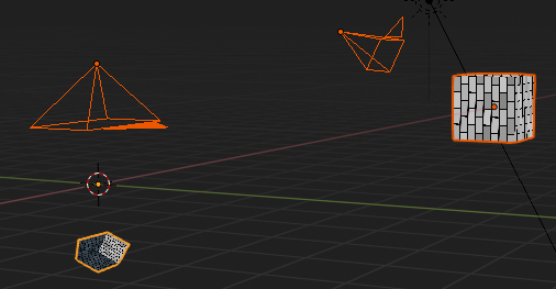
There is a way to do this with Python scripting. I have two versions of my test object: The original version, and a duplicate version that gets transformed before it is rendered. I have a perspective camera that determines how it will get rendered, and a second orthographic camera that is actually used to render the final image with the transformed duplicate.
The 3D transform is the part that requires programming. By running a Python script from the text view in Blender, you can set the coordinates of the duplicate model based on the original model. Luckily, there is a single function called world_to_camera_view that does everything we need.
Note: This only works immediately after making the duplicate because the order of the vertices and polygons is the same in both models. If you change any of the topology of the original model, you need to make another copy or it won’t work properly!
Here is the actual script to transform the vertex coordinates:
# Transform the vertices from an object from a camera view
# and set those positions on another object
def TransformObject(camera, scene, object, orthoObject):

    # Object data
    mesh = object.data
    orthoMesh = orthoObject.data
    matrix = object.matrix_world

    # Image data
    imageWidth = scene.render.resolution_x
    imageHeight = scene.render.resolution_y

    for poly in mesh.polygons:
        for idx in poly.vertices:
            pos = matrix @ mesh.vertices[idx].co

            # Transform from 3D space into normalized camera space
            # For on-screen vertices, this returns a vector from (0,0,z) to (1,1,z)
            pos = bpy_extras.object_utils.world_to_camera_view(scene, camera, pos)

            # Center to the ortho camera
            pos.x -= .5
            pos.y -= .5

            # Scale by the aspect ratio
            pos.x *= (imageWidth / imageHeight)

            # Scale the depth so it will sort  properly
            pos.z *= -0.2   # Use any negative value here

            # Set the position
            orthoMesh.vertices[idx].co = pos
Depending on the look you’re going for, you can either stop there or add more effects to make it look more authentic.
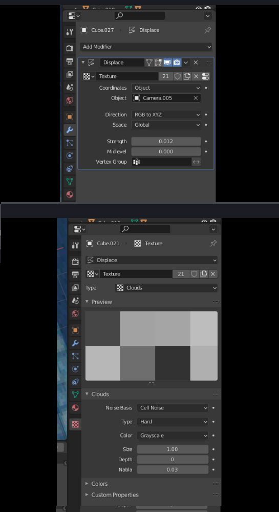
If you run this function you will notice that the transformed positions get flattened and stretched depending on the distance to the camera, so if you try to light this scene using regular lights it will get completely distorted. In my scene I have some rudimentary lighting, but it is actually faked in the shader. I added vertex colors to the duplicate model and set up the shader to multiply by the vertex colors, then I added a bit of extra code to add fake sunlight based on the direction of a sun object:
# Global settings
g_useLighting = True
g_lightColor = mathutils.Vector([1.0, 0.9, 0.8])
g_ambientColor = mathutils.Vector([0.25, 0.3, 0.35])

def TransformObject(camera, scene, object, orthoObject, lightObject):
    # Object data
    ...
    rotationQuat = object.rotation_euler.to_quaternion()
    colors = orthoMesh.vertex_colors.get('Col')
    lightDir = lightObject.rotation_euler.to_quaternion() @ mathutils.Vector([0,0,1])

    ...
    colorOffset = 0
    for poly in mesh.polygons:
        for idx in poly.vertices:
            ...
            # Do fake lighting on the transformed model
            normal = rotationQuat @ poly.normal
            totalLightColor = mathutils.Vector([1,1,1])
            if (g_useLighting):
                brightness = max(lightDir.dot(normal), 0)
                totalLightColor = g_ambientColor + (g_lightColor * brightness)

            colors.data[colorOffset].color = [totalLightColor[0], totalLightColor[1], totalLightColor[2], 1]
            colorOffset += 1
.
Rounding vertex coordinates
The PlayStation also rounded each vertex coordinate to the nearest pixel in 2D space, which added to the wobbliness of the polygons. Once we have the perspective transform, it is very easy to add this to the Python script with a few extra lines:
            # Round the position to the nearest pixel
            if (g_roundPixels):
                pos.x = (int)(pos.x * imageWidth) / imageWidth
                pos.y = (int)(pos.y * imageHeight) / imageHeight

            # Center to the ortho camera
            ...
Here is the final script, including an event callback to make it update whenever the frame changes:
#
# PlayStation-style view transform script by Komojo
#

import bpy
import math
import mathutils
import bpy_extras.object_utils

# Global settings
g_roundPixels = True
g_useLighting = True
g_lightColor = mathutils.Vector([1.0, 0.9, 0.8])
g_ambientColor = mathutils.Vector([0.25, 0.3, 0.35])

# Transform the vertex positionson an object from a camera view
# and set those positions on another object
def TransformObject(camera, scene, object, orthoObject, lightObject):

    # Object data
    mesh = object.data
    orthoMesh = orthoObject.data
    matrix = object.matrix_world
    rotationQuat = object.rotation_euler.to_quaternion()
    colors = orthoMesh.vertex_colors.get('Col')
    lightDir = lightObject.rotation_euler.to_quaternion() @ mathutils.Vector([0,0,1])

    # Image data
    imageWidth = scene.render.resolution_x
    imageHeight = scene.render.resolution_y

    colorOffset = 0
    for poly in mesh.polygons:
        for idx in poly.vertices:
            pos = matrix @ mesh.vertices[idx].co
            normal = rotationQuat @ poly.normal

            # Transform from 3D space into normalized camera space
            # For on-screen vertices, this returns a vector from (0,0,z) to (1,1,z)
            pos = bpy_extras.object_utils.world_to_camera_view(scene, camera, pos)

            # Round the position to the nearest pixel
            if (g_roundPixels):
                pos.x = (int)(pos.x * imageWidth) / imageWidth
                pos.y = (int)(pos.y * imageHeight) / imageHeight

            # Center to the ortho camera
            pos.x -= .5
            pos.y -= .5

            # Scale by the aspect ratio
            pos.x *= (imageWidth / imageHeight)

            # Scale the depth so it will sort  properly
            pos.z *= -0.2   # Use any negative value here

            # Set the position
            orthoMesh.vertices[idx].co = pos

            # Do fake lighting on the transformed model
            totalLightColor = mathutils.Vector([1,1,1])
            if (g_useLighting):
                brightness = max(lightDir.dot(normal), 0)
                totalLightColor = g_ambientColor + (g_lightColor * brightness)

            colors.data[colorOffset].color = [totalLightColor[0], totalLightColor[1], totalLightColor[2], 1]
            colorOffset += 1

def TransformObjects():
    scene = bpy.context.scene
    object = scene.objects['Cube']
    orthoObject = scene.objects['Ortho Cube']
    lightObject = scene.objects['Sun']
    camera = scene.objects['Camera']
    TransformObject(camera, scene, object, orthoObject, lightObject)

def updateHandler(dummy):
    TransformObjects()

# Set a callback to update the transform when the frame changes
bpy.app.handlers.frame_change_post.clear()  # Warning: This might also delete other callbacks
bpy.app.handlers.frame_change_post.append(updateHandler)

# Update now
TransformObjects()
.
Pixelated graphics
By default, Blender will render with a high sample count which will appear as anti-aliasing. To make it actually look pixellated, first set the image to a low resolution (I’m using 320x180) and then go to the render settings.
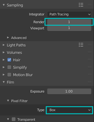
For Cycles, set the number of samples to 1 and then go to the Film settings and change the Pixel Filter type to Box. (The default type adds a bit of randomness per pixel.)
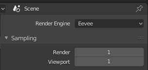
For Eevee, set the sample count to 1.
Also make sure to use nearest neighbor filtering on all your textures.
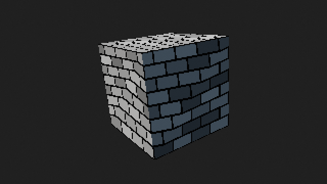
If you look closely at my test image, you can see a bit of anti-aliasing on a few of the pixels…I’m not sure what’s coming from, but if you’re just trying to mimic the effect I think this should be close enough.
Here is the blend file. Hope this helps! 
psx.blend (751.8 KB)