All the principles are based on a video by zircron45, so if you haven’t seen it yet, watch it first. In his video he creates real lenses based on optical design blueprints and images from other sources.
Me being me, it was not enough, so I decided to bring geometry nodes into this and make a somewhat accurate system, albeit with limitations, that would allow me to create lenses using only patent numbers such as radius, distances, etc.
This could be done with coding, but I think geometry nodes are a simpler solution and can 100% be paired with scripts for presets or simple setup process if needed.
Some of the limitations at this time are:
The housing for the lens is set manually (ideally it should be automatic)
Trimming the lenses to the desired height is unfortunately done with sliders (there is almost no data for this in the patent, so everything is done using blueprint as a rough measurement)
The same for aperture placement.
CA simulation options should also be explored. Cycles failed tests with white noise textures and/or a separate shaders for each color. It produces so much noise already on the second lens element that it’s barely usable (maybe some of you have suggestions for other methods, I know LuxCore handles this a thousand times better, but the point is to do in Cycles.
Need friendlier control over focus, aperture, and other things.
Might be possible to implement aspherical lenses and other stuff.
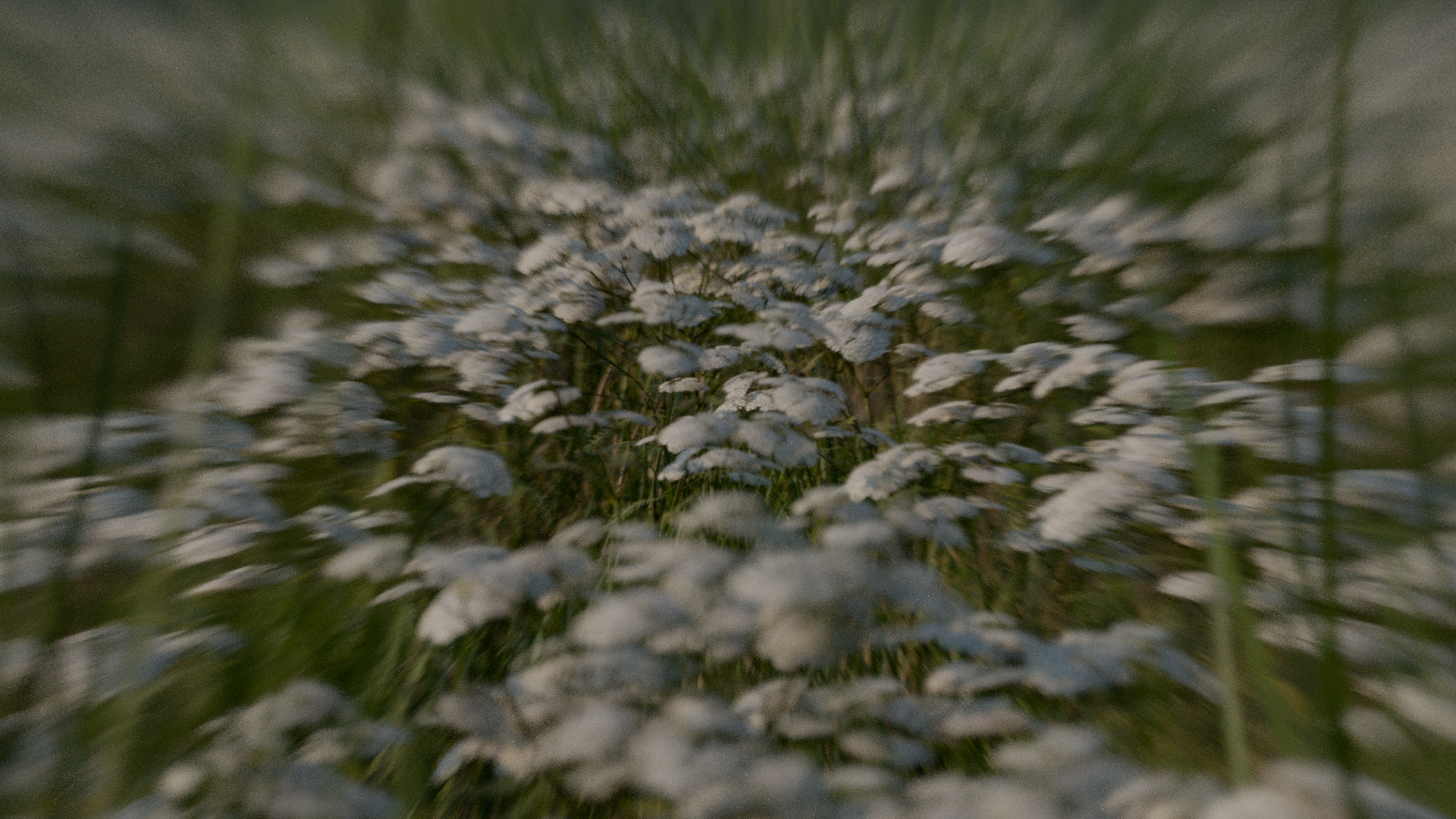
From my observations, the noise patterns are somehow much nicer with this method of camera simulation than with regular digital noise, maybe it’s just a coincidence.
There is also still a ton to explore with different lenses and many more features to implement.
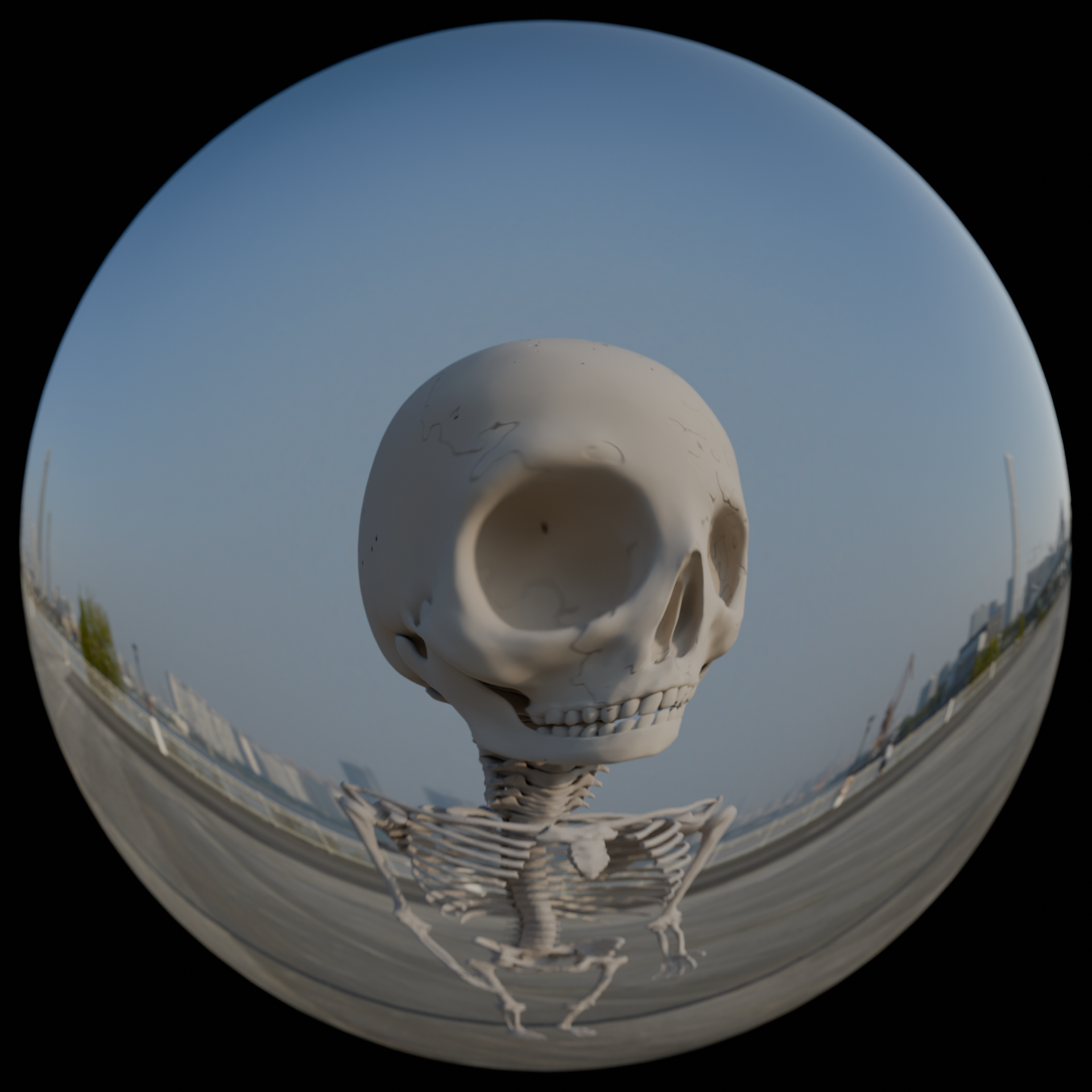
I will attach the files of my experiment. There are two lenses in the blendfile. I forgot the name of the second one, but one of them is an old Nikkor 6mm fisheye lens.
I’ve registered here specifically to tell you that you’re my hero
I’m very happy that this exists, cause I want to try the method out; I’m a bit experienced with photography, but modelling a lens with a high degree of failure was intimidating.
I’ve opened your blend file and I’m curious on what should I change to be able to experiment. The radius, IOR and distance are kinda self-explanatory, but how do I add more lens blocks myself? How do you realize the two layers with a thin film that Zircron45 shows in his tutorial? How do you adjust the focal plane correctly, is there a figure for that as well?
Also, do you reckon the lens HAS to be that big?
In any case, I would love to play more with it if I understood more about it.
Thank you very much for your work!
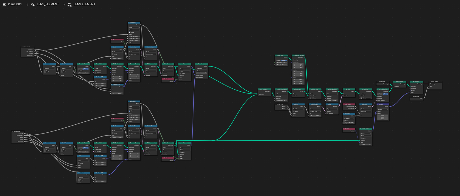
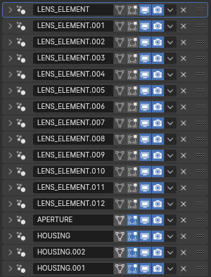
Hey, thanks! Glad I could help somebody. The building of the lens is done by stacking modifiers on top of each other, so 1 modifier = 1 lens block, I made it that way so it automatically spaces itself correcly between each block. There is also modifiers in the stack to create housing and aperture with blades setting
About a thin film, I think you are reffering to two blocks that are stuck together. The solution is to make “Air Distance” some value close to zero, but not actually zero because it would cause artifacts (somewhere around 0.0001 is what I do)
I couldn’t find any numerical values in the patents to implement it automatically, if there I would be happy to add in the files! Or maybe some mathematical genius could step in to help. So for now its just eyeballing what looks best.
The size doesn’t matter, but with resizing it, you should also adjust the focal plane. One thing I noticed is that sometimes “too small” exists, but yeah it can aboslutelly be smaller if it doesnt fit in the scene properly
Fantastic, you gave me more confidence to go in and try it, and thank you for the swift response, too.
It’s actually getting me closer to a thought that I once had: sketching out a scene for a livestream in blender while using the approximation of my real lenses. I don’t know if I’ll ever get to that, but!
Great Work. Thanks a lot.
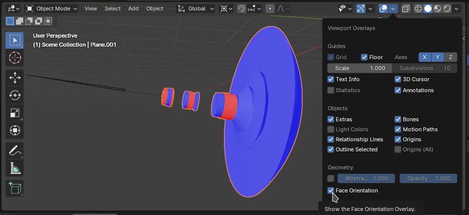
I looked a bit to your setup and recognized that the Flipnormal Node is buggy. As result you got some flipped faces.
Deactivating it solves this Problem.
Thanks! The Flip Normal inpit is supposed to be a manual switch in the case the lens element is concave, or one side is curving in the opposite direction (so the signes of the radiuses are different. That way it will be correct for such lens designs
Hey, yeah this is hard to explain, but visually illustrated by the video I mentioned, check out this time code.
So the correct face orientation for convex lenses is actually inverted, thus the initial setup is correct. I added the switch just for debugging and experimenting!
I stumbled across the same video by zircron45 and had the same Idea as you while looking for fixes I found this thread but your file isn’t online on google drive anymore
would you mind sharing it again?