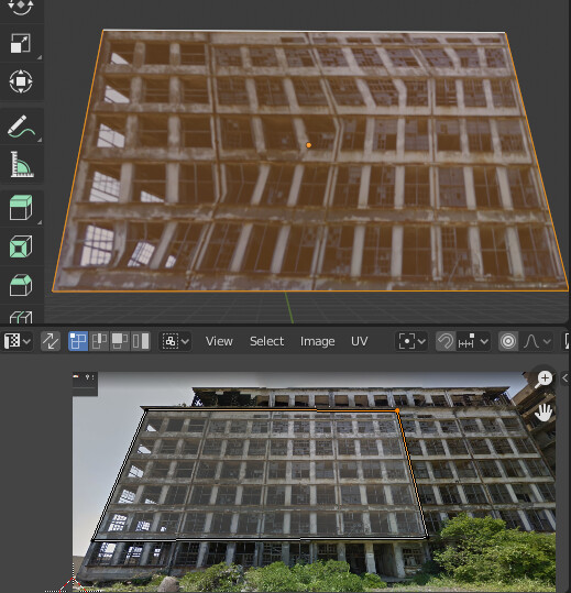
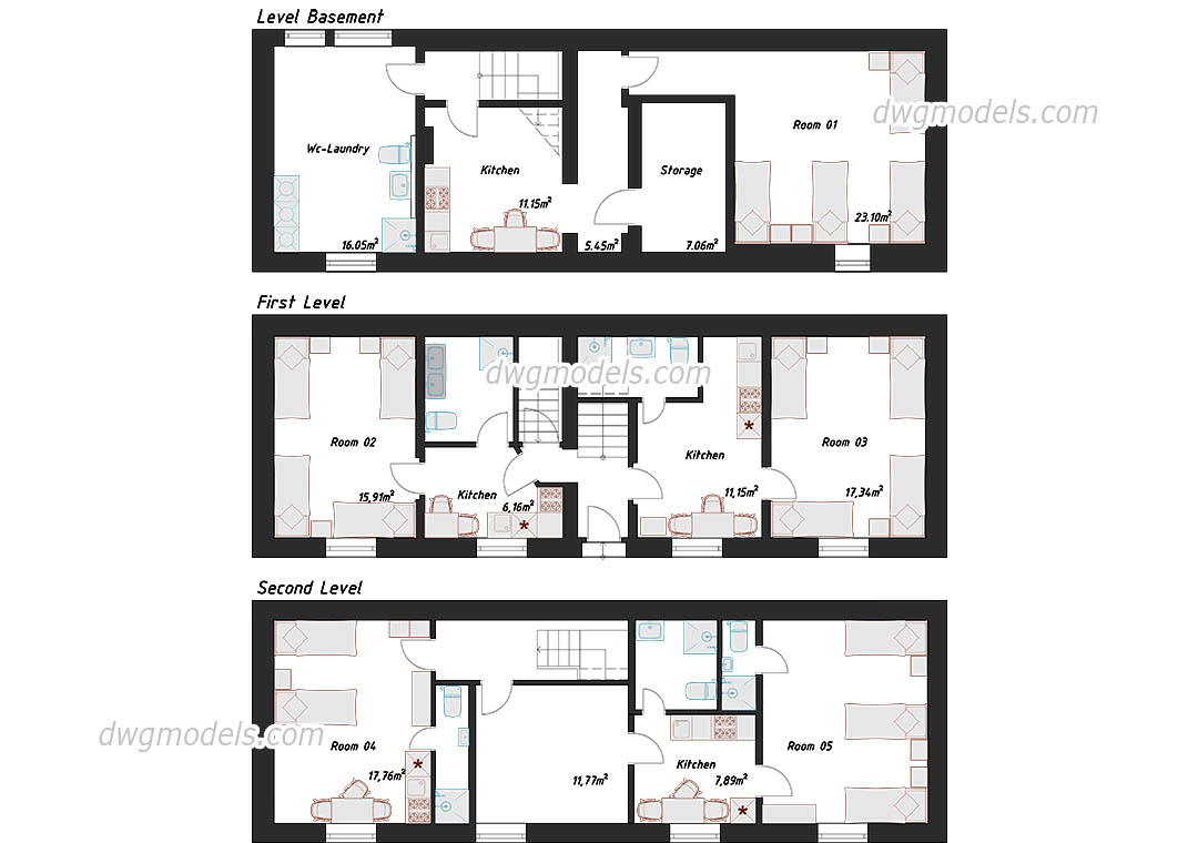
I create floor plans for various projects from time to time. The floor plans are often in 3D, but sometimes they should be in 2D. For the 2D views, I always have difficulties “drawing” the stairs. I have tried to use an image or a texture, but stairs are not all the same length, width, etc. and the images get distorted. I have no idea how this works in AutoCAD, for example. Using the word AutoCAD, I have only found so-called CAD blocks, which in turn are images.
Ideally, I have a face that I select and I can use a modifier or another add-on to create curves with geometry on the face so that it symbolizes a staircase.
I am also not averse to doing this via geometry nodes. But unfortunately I have no experience of how to implement this.
It would also be okay if the staircase is actually 3D and the modifier or add-on would create the correct lines or curves based on the 3D information. That would probably be best, as I usually want to display the 2D floor plan in 3D as well.
Standardized stairs can be made in advance, registered as assets, and brought when necessary.
Standardized stairs are possible, but non-standardized stairs will have to be drawn every time.
※ Everything that is standardized can be registered as an asset in advance and used.
I think I know what you mean. But I don’t think there are really standardized stairs. Every staircase I’ve had so far has had at least a different length. If you take an image texture that has an arrow at the end of the staircase, for example, then this arrow is always distorted. This is even more noticeable with the typical circles at the beginning of a staircase.
Stairs follow the standard rule of 7-11. 7" of Rise to 11" of Run, or slight deviations of the rule like 8" Rise to 10" of Run…
There are non-standard stairs in landscape or where it is a small distance of rise and the run is extremely wide ( like in landscaping ) but when this happens or is used on a higher unit of rise, it becomes uncomfortable to walk on… and is a dangerous tripping hazard…
Here is a stair Calculator that will give you the dimensions of the tread and height of a stair ( usually use total rise and total run with a set run dimension).
Thanks @oo_1942 for the hint. However, my problem is not the distortion per se, but the fact that if I use an image for the stair texture, the image will be distorted if the stairs are much longer or wider than intended for the image, for example. If you have the typical circle at the beginning of the steps and an arrow at the end of the steps, these two symbols would be distorted.
Thank you @RSEhlers for the knowledge. I am aware of the rules for step size. In the metric system it is 30x16cm. But not all stairs have the same number of steps. The same goes for width. While 90-100cm seems to be a defacto standard, there are many stairs that have other dimensions. Especially in older houses. It would be difficult to create a template for every situation.
I know how to create responsive CAD block style stairs manually with curves or meshes, but to me it feels like a repetitive step over and over, so although I’m not a programmer, I thought it might be possible to automate this in some way.
For example, you could lay out the space that the staircase occupies with planes and then press a button (or apply a modifier) that triggers some sort of automation that turns the plane(s) into curves with geometry and then optimally applies the defacto default rules.