This one is a bit tricky. It takes a bit of work but it is possible to do in Blender.
Part 1: The “easy” method
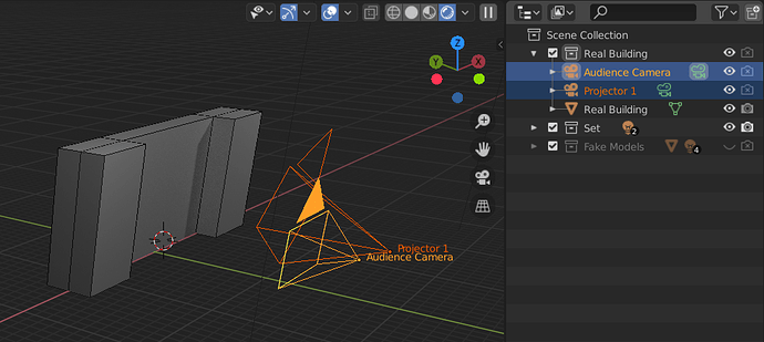
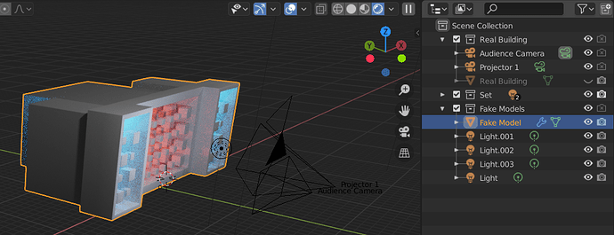
Here’s a test scene I set up to answer your question. There is one collection that has a model of the real life building, and another one with the fake animation to be projected onto it.
What you need to do is render the scene once from the point of view of the audience, and then again from the point of view of each of the projectors using the image you rendered from the first view.
Step 1: Render the audience view
First select the audience camera as the main camera (Ctrl+0) and render the animation with a field of view that encompasses everything in the scene. Toggle the render settings so it renders the fake models but not the real life building model.

Save a copy of this image/animation.
Step 2: Render the projector views
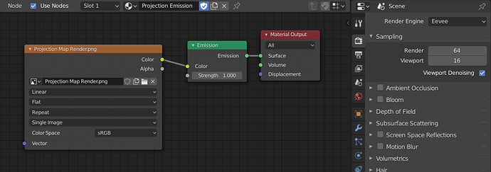
Now hide the “fake” collection and go back to the real world model. Create a material that uses the previously rendered animation/image as an image texture.
Now to get the texture to line up: Set the view to the audience camera (0 or Ctrl+0) and then select the real building model and go to the UV unwrapping view. Select all of the faces in edit mode, then press U and select “Project from View.” You should see the UV coordinates lining up with the rendered view.
Now it has an emission shader that shows the same locked perspective even when you change to different angles.

To render the proper perspective you need a second camera that is aligned to the focal point of the real world projector (I’m assuming you have measured this.) Select the projector camera view with Ctrl+0 and render the building. Since it is just using the emission shader we can use Eevee for fast rendering.
That should get you most of the way there, except for a few specific issues that you might need to worry about with this sort of thing.
Part 2: More advanced stuff
2a. Perspective distortion
If you are only getting the texture coordinates from UV mapping, it will translate the textures using affine maps, which can can cause a weird wobbly effect in the textures in some situations. This is the same effect that causes jittery polygons in old PlayStation games. It is possible to mitigate this by subdividing the model, but you can also make a shader that will do correct perspective for every pixel. Here’s a version I came up with:
I was going to write a detailed explanation of how this works, it might be more complicated than what you need.
2b. Color Management
If you render the animation using the Filmic settings (enabled by default) it might end up with a slightly different shade after rendering a second time from the emission shader, since it is trying to apply the same color transform twice.


There is a setting for the color management in the Scene tab, and another setting for the color space in the texture input node in the shader. The output of your animation render should match the input of the texture node. I could be wrong on this, but I believe you can use either of these settings as long as the input matches the output.


