bugloop1.blend (2.44 MB)
i have a 2D dwg for a propeller and not certain how to read it and do the 3D model
anyone can help with this
happy blendering
bugloop1.blend (2.44 MB)
i have a 2D dwg for a propeller and not certain how to read it and do the 3D model
anyone can help with this
happy blendering
Well, you really need an X, Y, and Z axis view. From this one view, your pretty much guessing at it.
Do you have teh actual DWG file?
Yo Rick
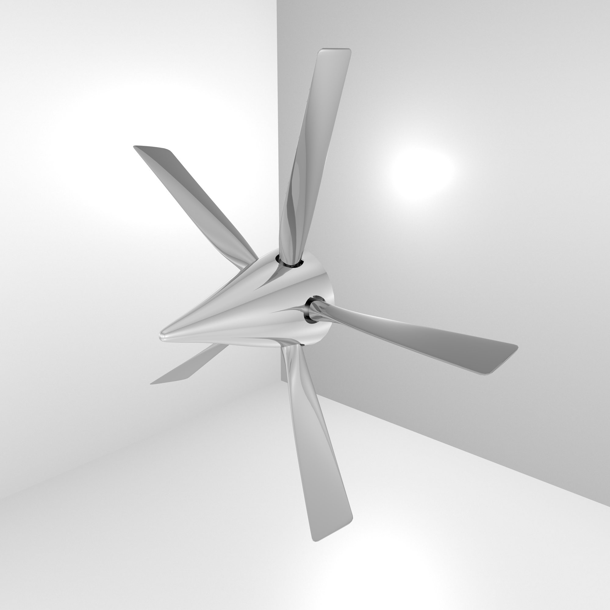
I am a true propeller lover and specialist, ask me whatever you want 
Here are some of my props
For your current problem, I don’t really understand … The best way is to start for a good airfoil shape, then extrude then change chord , get it thinner and thinner and rotate it some degrees on each extrudes to get the correct twist. A good blade can take up to 1 hour full modelling to get done perfect, it’s mainly due to how your eyes can recognize a well shaped blade or not… if not, it can take … forever
nice ones man
this is for my titanic project
so sorry it is not an airprop
but more a water prop
i’ll pm something
i have another drawing showing the tilt
but don’t know how to read it !
thanks
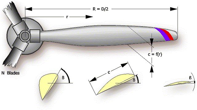
Propeller section functions as a wing to create lift. Propeller cross-section twists and flattens as it goes from hub to tip. This is because when propeller spins through air the tip is traveling much faster then the base. If you don’t account for this, propeller tip is going to generate too much lift. This can cause host of problems. You want to generate lift evenly along the blade.
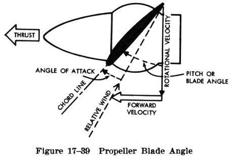
For given Thrust and Forward velocity, Rotational velocity of propeller cross section is going to be different at different radius. As you approach propeller tip this Rotational velocity become larger and larger. So to keep Angle of attack to the airfoil blade section constant, Pitch of blade need to get smaller and smaller to generate same amount of lift.
Water prop works the same. Water screw spin quite a bit slower because water is 800 times denser then air. Lifts generated are quite a bit larger. Thus the short stubby paddle like blade. But the idea is the same; cross-section twists and flattens as it goes from hub to tip.

i’m trying to get the 3D model from some 2D dwg
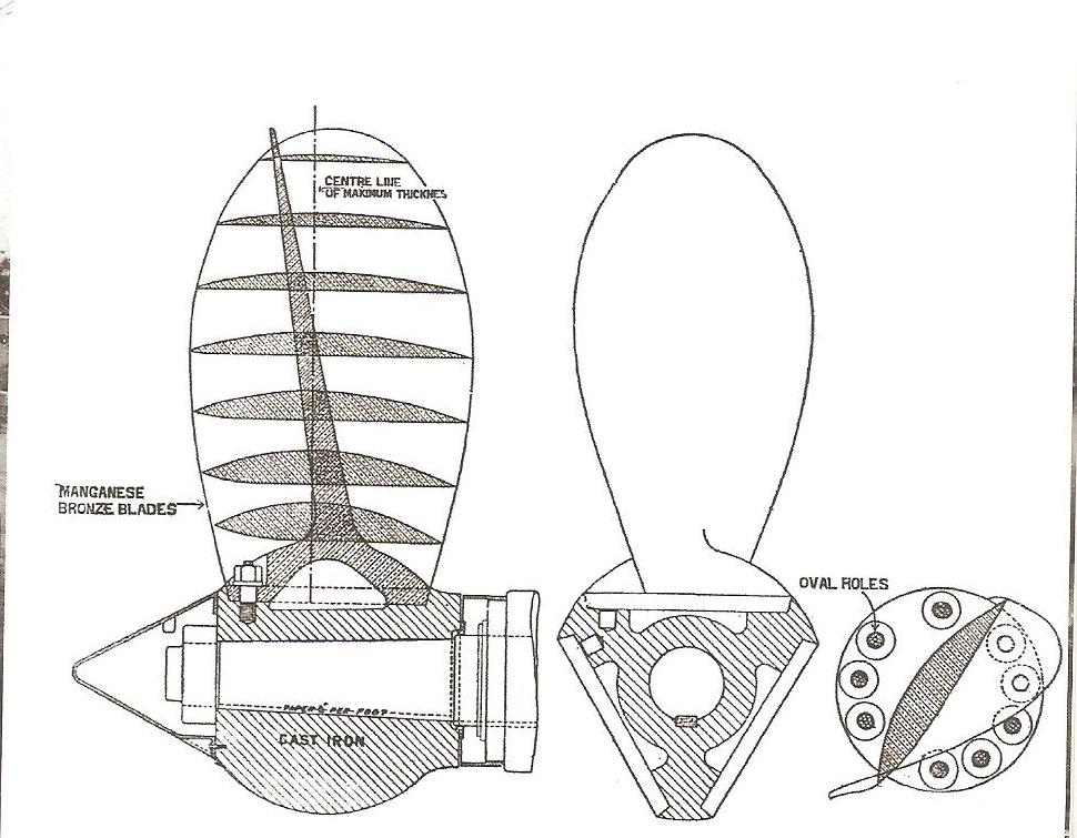
here is the 3 dwg
but i dont’ understand how these works to get the 3D model!
first pic on left has a slanted center line
so how does this works with the other dwg ?
i may have to add manualy more cross sections
to get better skinning
have to redo it with splines
and i’ll do the base hub manually
i already done the triple hub
did the surface spline in file
propeler4.blend (102 KB)
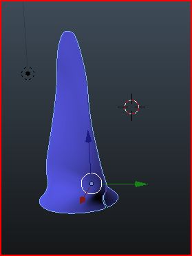
ths skinned surface is not good
it does not have the proper twisting
thanks
Ya this looks like crazy shaped speedboat prop. Look at the number of bolts that’s needed to hold that prop on to the hub, easily several tons of centripetal force on it! This prop is spinning like crazy.
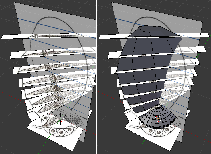
Anyway you can cut up the drawings, and lay it up using Empty image. Line then all up and you do need to play each image with scale to make them fit. I don’t know why but blender imports those images in all kinds of scales!?
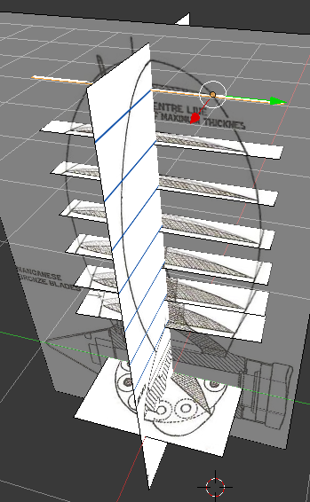
Once every thing is laid out, rotate those prop sections to fit the prop curves. I disabled Z movement to keep prop section images in plane as I played with it. Check against all views. Remember that prop sections pitch angle is large at the base, and flattens out at the tip. When it looks satisfactory put down 3D geometry right on it. Connect the dots.
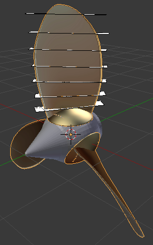
Here is how it looks in the rough. The views and prop never did lined up for me. Some of those views were not technically correct. Prop profile was just drawn in. Not accurate. Counter sunk holes for the bolt probably need to be manually created with loops. You can try Boolean but its going to be a mess. Creating fillet where prop meets the base flange is going to be fun too!
still difficult to see how to get the proper twisting
what would the vertical slanted part represent on left pic ?
we also see that the center line is not in the center of the left pic
not certain what this means here ?
thanks
one other thing here
if i set the base cross section at same angle then on the right picture for the top
i dont’ get same width then in middle pic !
which is strange!
thanks
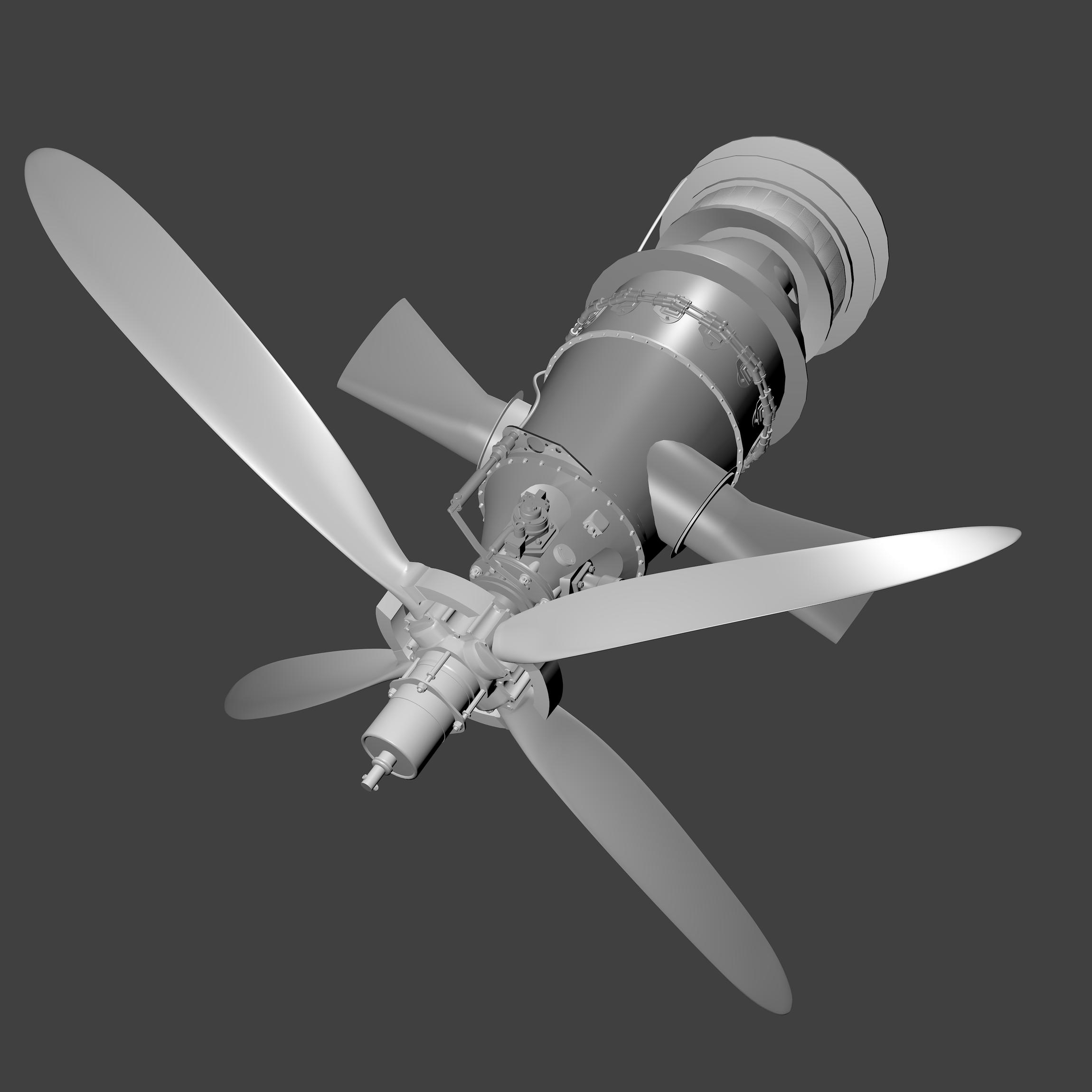
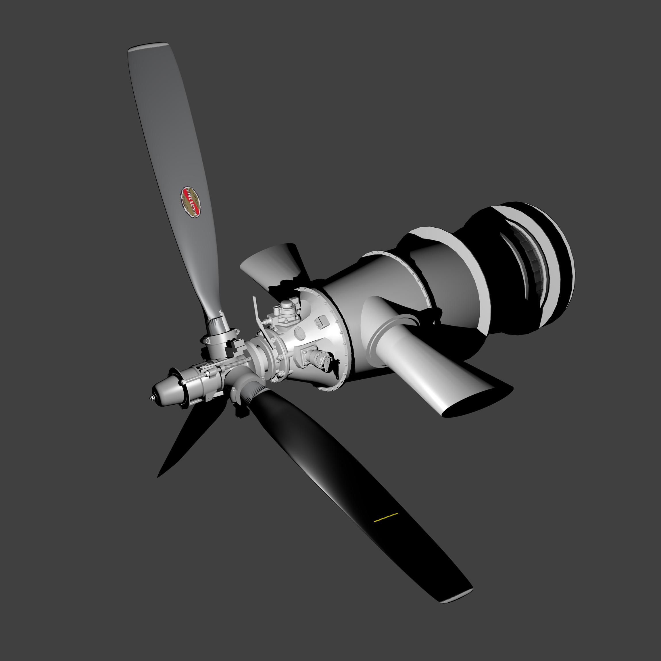
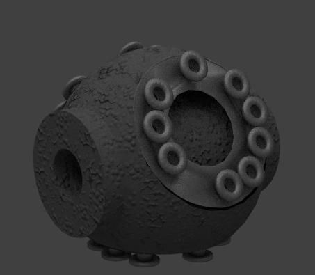
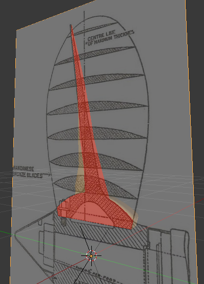
The vertical slanted part is the section figure of the prop. The section is made along the shaft seen from side. It describes cast iron hub geometry with prop assembled with bolt. Here is the section image of my prop model. It came out close to what the drawing shows.
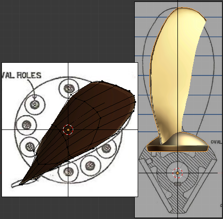
Here is Top and End view of blade. I assumed top view is more accurate. Those leading / trailing edge of blade seems carefully laid out. The end view of a blade never looked right. And those line never came close to prop edge.
The centerline of maximum thickness has to do with thickest part of prop blade section. It has to do with blade loading I am sure. Center of mass of blade section locates on or very close to it. All centers of mass need to be inline and perpendicular to hub centerline. That way when prop spins, forces are aligned and there is no tendency of the blade to bend and twist out of shape under spinning load.
i tought it would fit on all sides!
it looks like the center line is not in the center of the base circle !
i’ll think about it more
it’s a diificult one to figure out the twisting angle function of Z !
thanks
i was able to get the proper front and side cross section
but it is not a simple rotation of each section
thanks