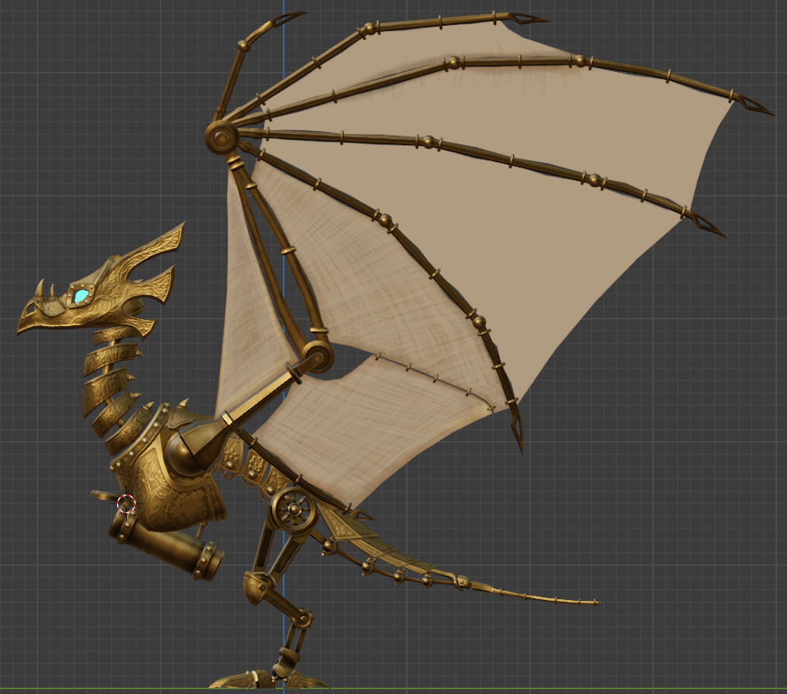
I’ve been working on a model of a clockwork/steampunk-style wyvern, and while it’s almost done, I’ve hit one major roadblock. All of its rigid parts have been rigged and the model is poseable, but the webbing of the wings, which are meant to be canvas stretched between brass frames, are giving me trouble. I’m still very new to weight painting, especially in Blender, and I may have bitten off more than I can chew.
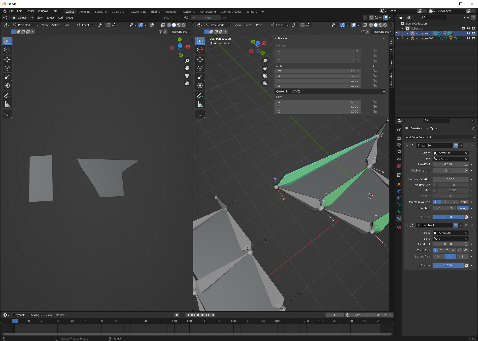
This is the model in side view (it’s symmetrical):
Is it worth trying to figure out how to weight-paint these the usual way? Or is there something that could simplify the process? Or, would I be better off just scrapping the canvas wings and trying something else? I was thinking about leaning into the magitech aesthetic and using floating crystals to fill the space between the wing fingers, but I wanted to try the canvas option first.
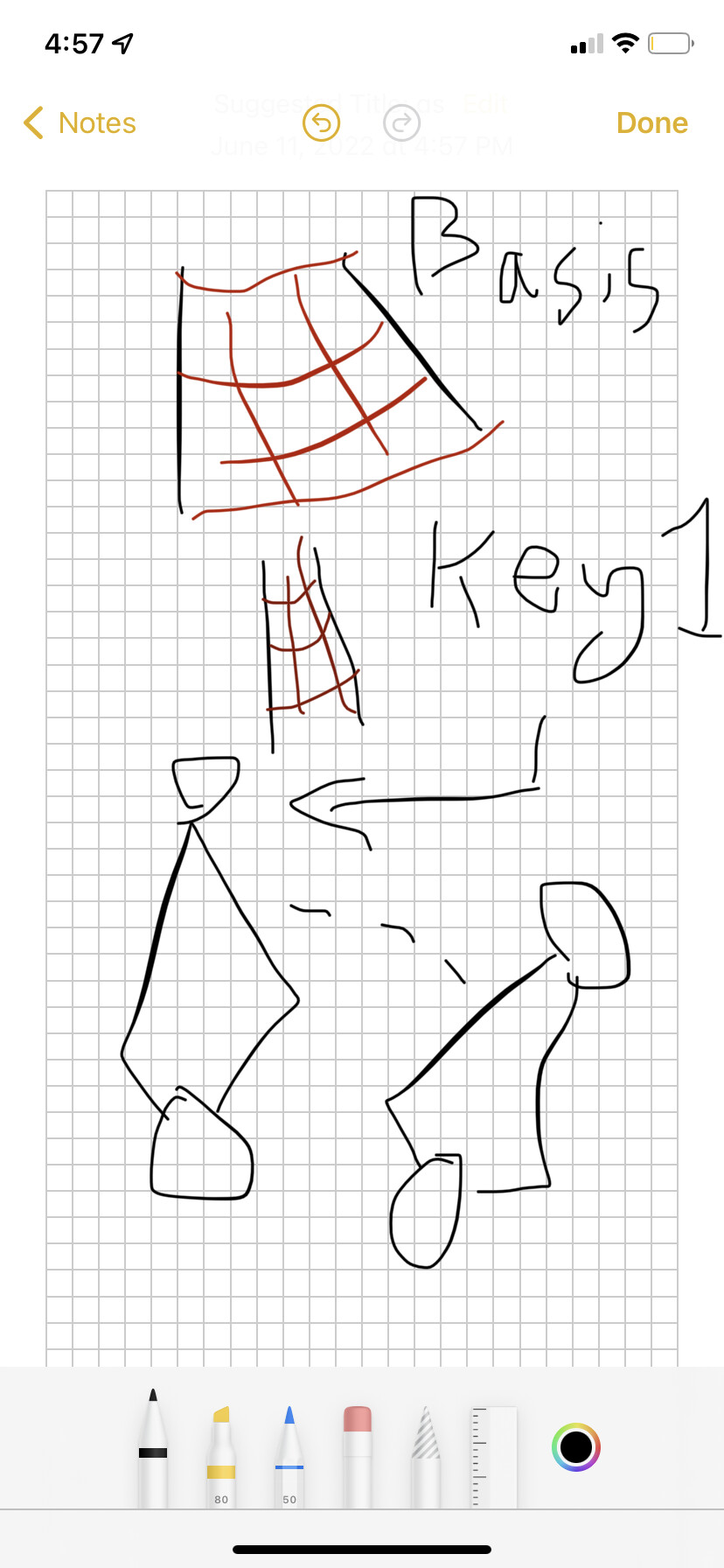
I’m going to be real with you, this is going to be horrible to weight paint. However, it should be super easy to use shape keys to do this- make one key for the canvas on the wings expanded, one for wings folded, and use a driver to connect the bones in the wing to the shape keys.
I’m on mobile, I apologize, normally I would whip up a quick Blende example of what I mean, but I don’t have my computer right now. But you can use the bone rotation to blend between the two shape keys. (You may need two keys per webbing, so each for drives one.) I would recommend sculpting the keys by hand- use the flat as the basis, and then use proportional editing to make the folded key
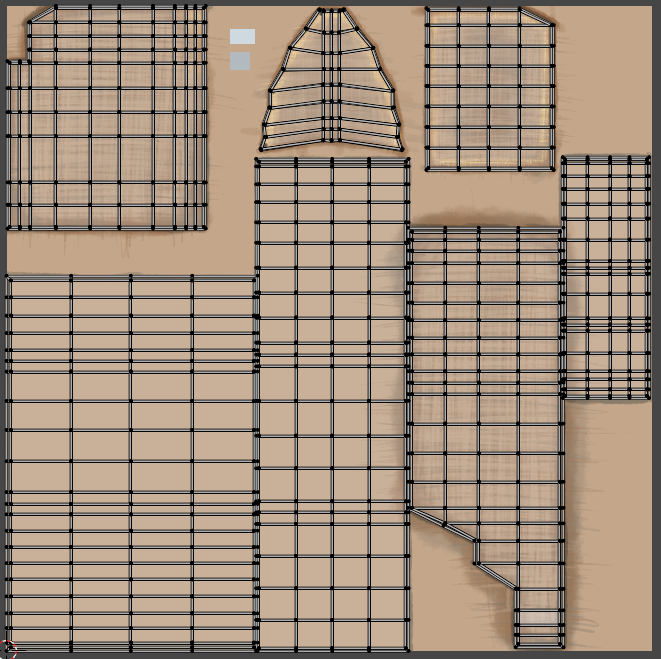
It’s a problem. Real cloth has spaces that expand when it stretches. Blender’s material nodes (or geo nodes, it could potentially be doable there) don’t give us the tools we’d need for that to happen. We could use OSL (which has the deltaUV/deltaPos we’d need to measure stretch dynamically) which could probably handle the problem. If you don’t know OSL, or you don’t want to spend days doing a CPU render, you live with it, and unwrap in a middle- or high-stretch position.
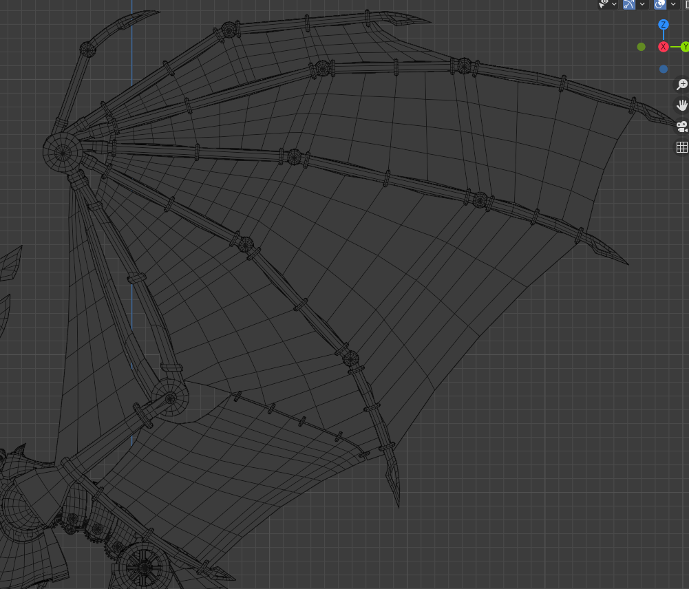
When I made a model with webbed wings, I went with simplest topology possible and inserted loops in the most expected stretch direction. Nowhere accurate but works
Geometry Nodes have a node that measures face area, so it should be possible to calculate squash and stretch factor and record it to custom attribute for use in a shader. Only complication may be is that you’ll need 2 geonode modifiers: one to put below Armature or whatever is deforming a mesh, in order to record the initial face area, and another above Armature to actually perform the calculation. Since Geometry Nodes dosent have anything that lets you “initialize” certan vartiables once; it will always update as the mesh deforms.
Separate between U and V will require more work, right. I indeed do not know how to calculate tangent properly. I thought about single float attribute, to perhaps fade the details of canvas texture based on stretching
Matter of preference, I guess. Still jumping through hoops compared to official modifiers, which have something like “bind” command for such cases
Sorry for the delay in replying, but would you still be able to do that example file? I’m reading up on shape keys and drivers, but I’m not sure how to apply the technique to my project.
Also, if I manage to get one wing set up, how difficult would it be to mirror it over to the other wing?