Hi all. I am struggling rigging a window shutter automation which model is somewhat complicated.
Actually, rigging may not be the right solution for what I’m trying to do, but I see no other solution.
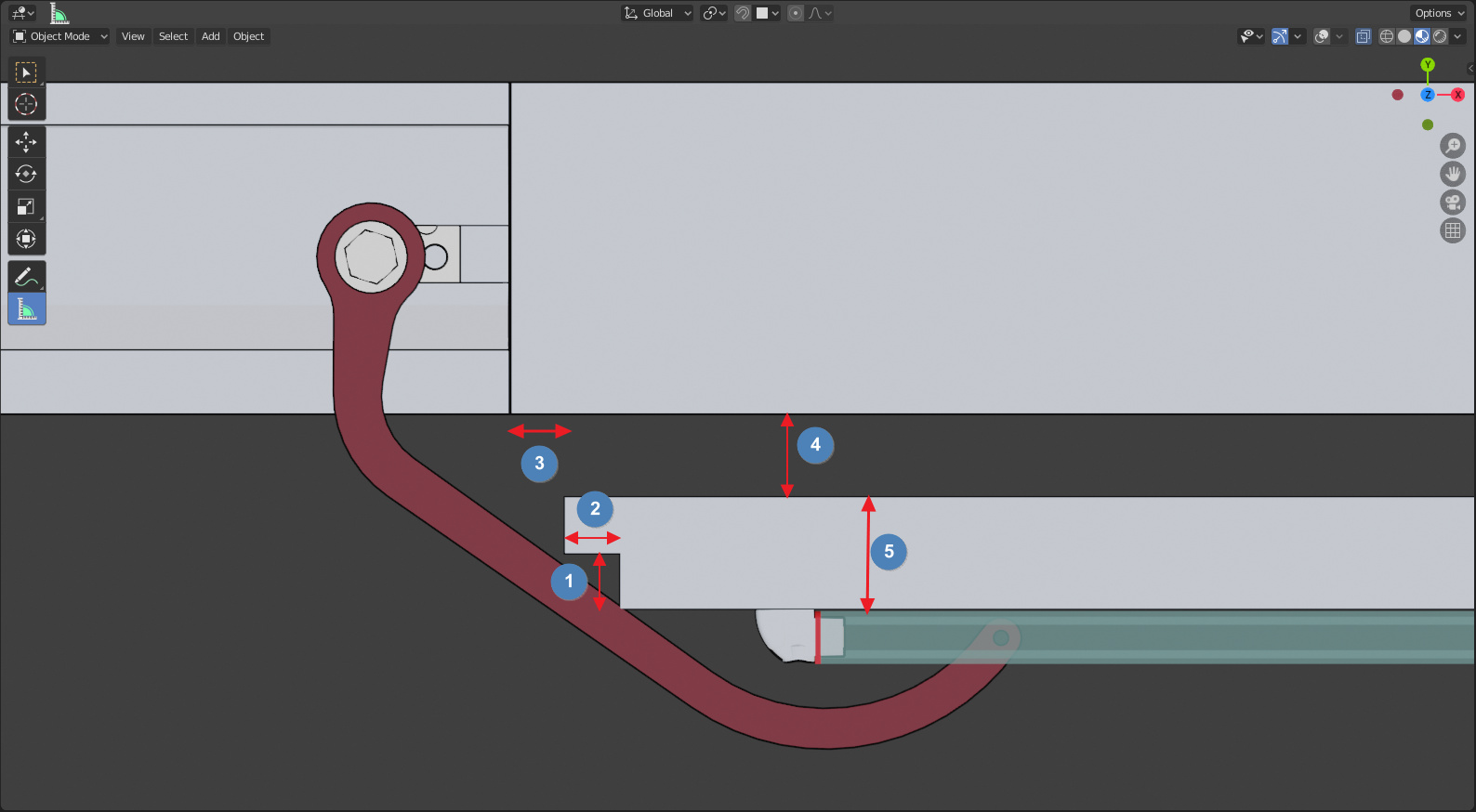
Basically, the model has drivers so that the shutter shape, based on the values of 1, 2 3, 4, 5 can be modified (depth of the recess on the Y-axis, depth of the recess on the X-axis, distance of the sutter origin - the corner - from the X-axis wall, distance from the Y-axis wall, shutter thickness). The sliding guide is moving so that it is always in contact wit the shutter face.
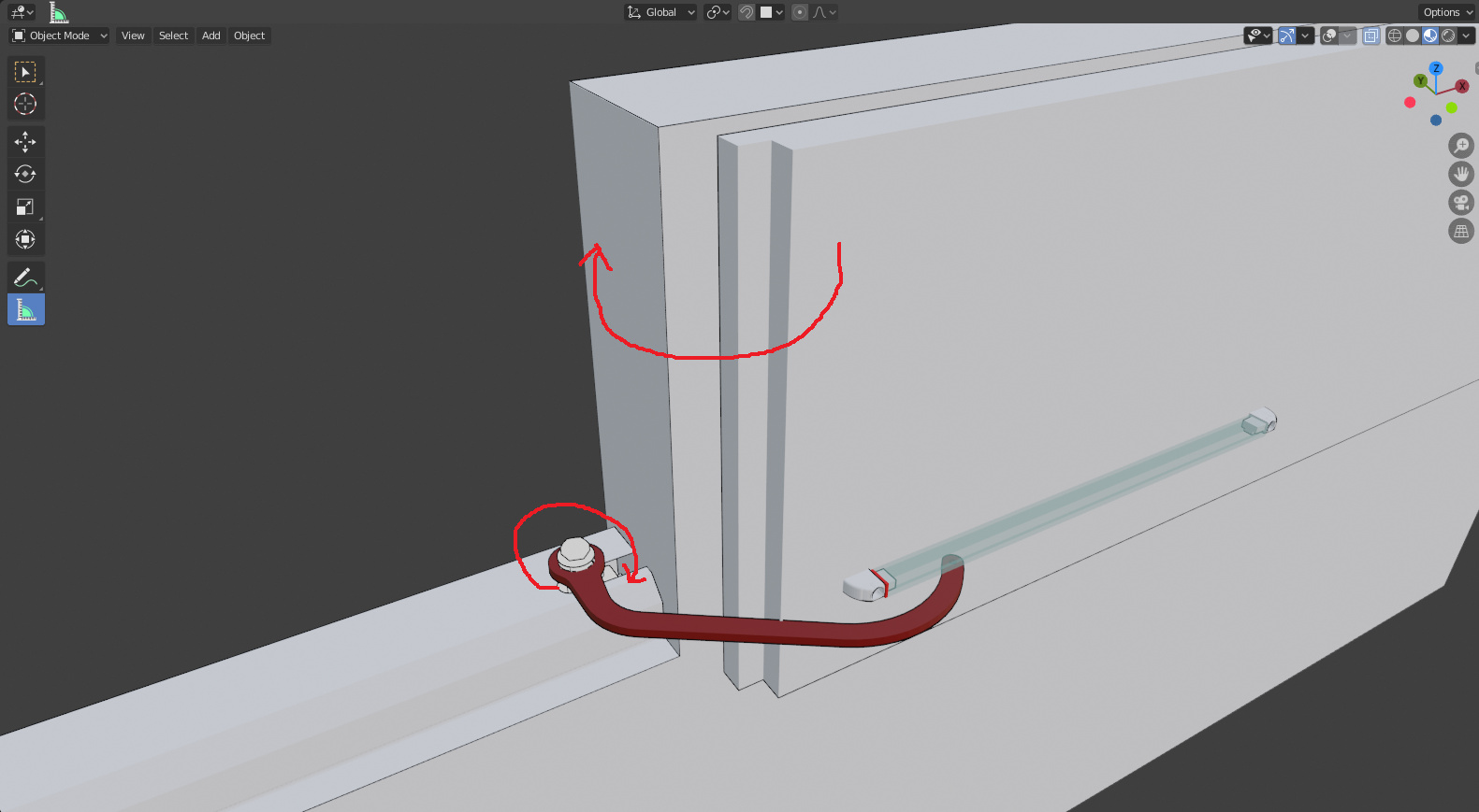
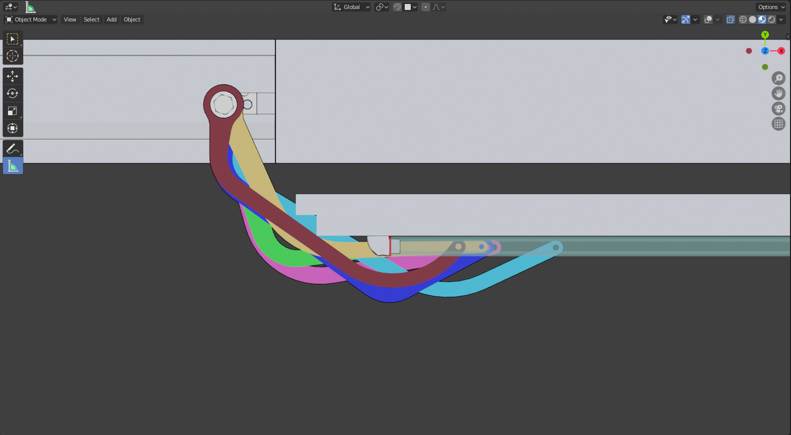
I have multiple types of arm to choose between, and when I modify the shutter shape and position, I need the front hinge of the arm to remain in line (on the Y axis) with the guide. If this is possible, then I can verify whether an arm fits better than another or interferes with the shutter (e.g. the light blue one).
Ideally I would like to rig everything so that the shutter can be opened and closed, but the main concern is to fit the arm’s front hinge on the guide regardless of the guide position (which is variable due to possible different values of 4 and 5)
Thank to whoever can help me making a step forward…
Had posted this request quite a long time ago, but then I had to delay the project and now I decided to stick to standard blender to make things easier (and I actually managed to do the parametric modification in a short time using custom properties), not to mention the “death” of BGE…
You could go a couple different ways. Not 100% sure the overall movement of the shutter (where it pivots?). But a hinge with a guide you could either use bones for the movement (parenting the mesh objects to them), or try object constraints.
A real basic way would be with bones and bone constraints, and a nurbs path object.
If you need a hinge to follow a track, you could map out bones to your meshes. Then with bone constraints, have the hinge bone “track to” the guide bone, the guide bone you “clamp to” a nurbs path object that runs along the sliding track. Then have the nurbs path, sliding track mesh, and shutter mesh all parented to another bone that runs along (mimics) the shutter.
Most of your bones you’ll need un-parent from each other (go to edit mode, Bone Properties>>Relations, X out the parent bone to sever the parenting link. So they aren’t effecting each other in a hierarchy.
Here’s an example file of a hinge with track. Really rough, so not precise, comes off the track at one point. I’m also assuming this is sort of what you’re looking to do. But hope it helps, or at least gives you some ideas.
I checked and unfortunately it doesn’t work, not only because the tracked bone exits the guide. The fact is, that I can’t use a simple “Track to” constraint, because the tail of bone 1 must remain inside the rack guide, not simply pointing to it. Bone 1, as well as the mesh associated to it, can’t stretch. Banging my head against the wall
My file was merely a rough example, not specific to your design, if that’s what you’re having problems getting to work. Just to give you the basic concepts and example of construction. And assumed you would build your own.
You mentioned having drivers in your file, assuming you’ve used them before? Another alternative if you’re stilling struggling with rigging would be to create a slider controller (or some kind of controller) that when moved, merely rotates the shutter and hinge at different speeds, then in the driver’s graph editor tweak the keyframes so the tip of your hinge always stays within the guide, whenever you’re applying the controller. It’s not technically rigged to perfection that way, and would take more time, but at least might look and mimic the movement you’re after fairly correctly. And while making the controller, anytime the tip of the hinge looks like it’s moving out of the guide at certain points when moving the controller, you can edit the driver graph’s curves to compensate, until everything works.
As for multiple leaf shapes, you might have to create a rig for each design (or alternatively driver controller for each design). Otherwise it would be far too complicated to have rigs changing shape to compensate for multiple pivot points.
There are so many possibilities to be taken into account (as all the 5 quotes can be changed based on the Custom properties I set) that it is not possible to create a driver that’ll work with all the configurations.
I thought it would have beer simpler to create such sort of mechanism where something with a fixed length (the red arm) is pulling / pushing another one through a slider (the leaf), but I couldn’t find any constraint or setting (stretch, etc.) that allowed me to do this. I’m definitely not into rigging armatures (the things I’ve done in the past were either using basic constraints or simpler armatures (e.g. a piston opening a gate leaf, where you have an hinge on the piston, one on the leaf, but the piston will change its extension according to the leaf opening angle, without sliding into anything).
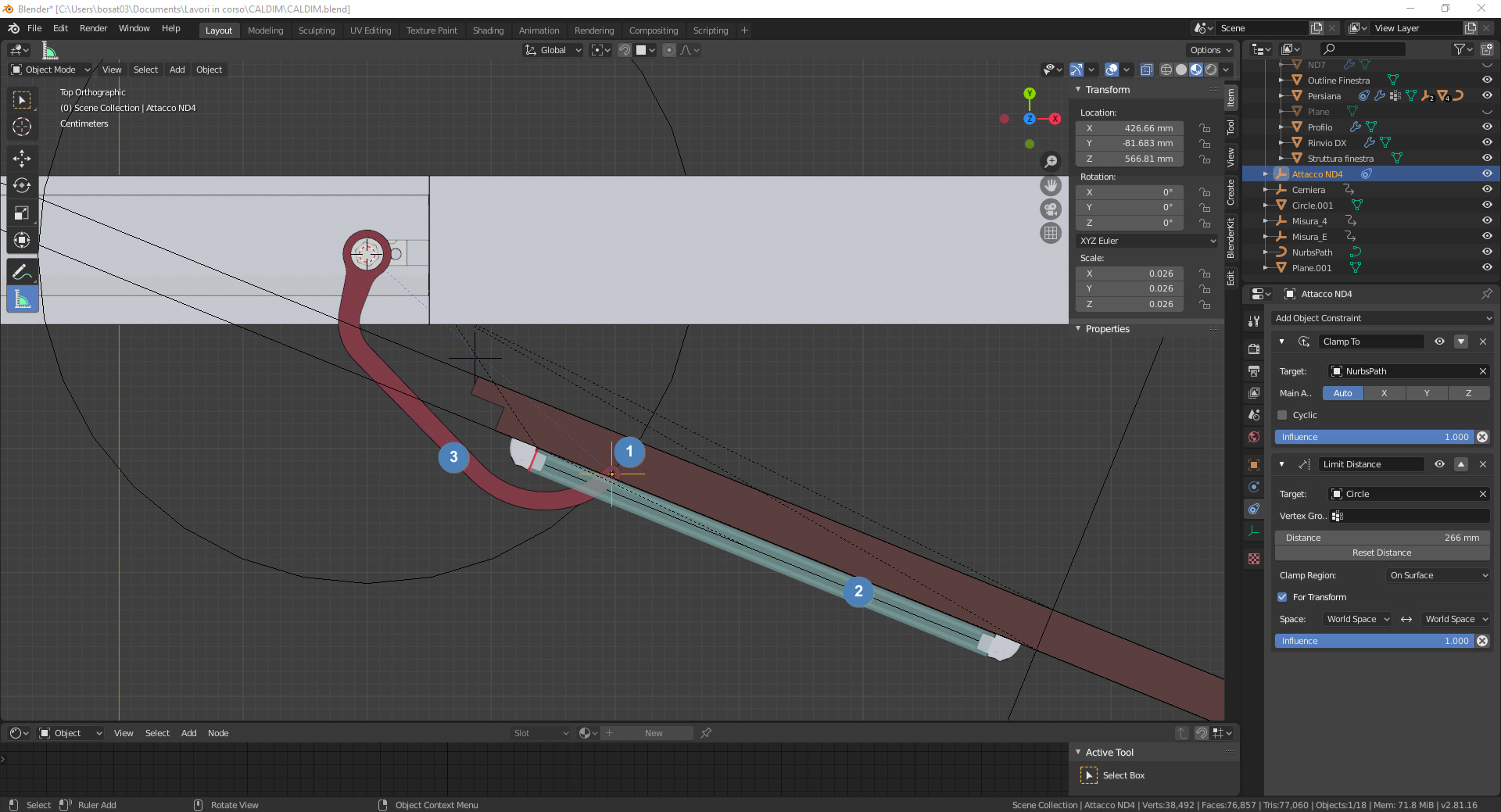
I found out that, were the constraints working as I thought/expect, there would be no need for the armature, as the whole rig can be done with just constraints. Having an empty (1) “Clamp to” the guide (2) (obviously, it would be a nurbs path parented to the guide to be able to clamp to it) and given a “Limit distance”, “on surface”, from the arm hinge (the distance corresponding to the arm’s centre-to-centre distance), and a “Track to” constraint on the arm (3), with one of the local axis oriented as the segment joining the two centers of the holes in the arm (plus using local space), I expected everything to work.
However, it doesn’t. The empty, just like your armature’s Bone 2, is either going very far along the nurbs path (if I disable the Limit distance - which could be understandable as I don’t know how the “Clamp to” works but in this case the empty is actually running along the path), thus jeopardizing the “Track to” functionality, or it does not stick correctly to the nurbs path if I enable the limit distance (a contraint that is obeyed by the empty in this case).
Should I change the constraints stack order, it screws up the “rig” and the arm doesn’t follow the empty position anymore except if quit Blender without saving and reopen the file…
Yeah, unfortunately if you have multiple variations of the shutter, with different positions of the pieces, pivot points are going to be in different places for whatever rig (bones or constraints) setup you have. I can’t think of a simple solution for you. clockmender’s example is a good start, but that setup seems to be reverse than what you need, so I could understand not making practical sense of it.
I did do a rough bone rig setup (little more complex), different from what I sent before. Again I’m not sure it’ll work with your setup (with the drivers), but it might at least give you some good ideas. If you try to recreate it, there’s some Bone Properties >> Relations / Inverse Kinematics settings I played around with. And I used a butt load of IK constraints. Not my cleanest rig, but it seems to do what you’re looking for:
Sorry for getting back on this topic so late. I can’t but thank for the work you made. However, despite clearly they’re not (as you and many other people seem to manage them so well), to me armatures are rocket science. I’ll never be able to replicate the same structure on 6 different arms and be able to also have drivers modify the bones position according to the quotes.
I came up with a totally different solution that on one side preserves the need for precision I have, on the other is much more understandable to my brain (though, I’m not sure it is for everyone). There’s just one little thing before I can call it completed, despite it’s actually fully functional (more on this later).
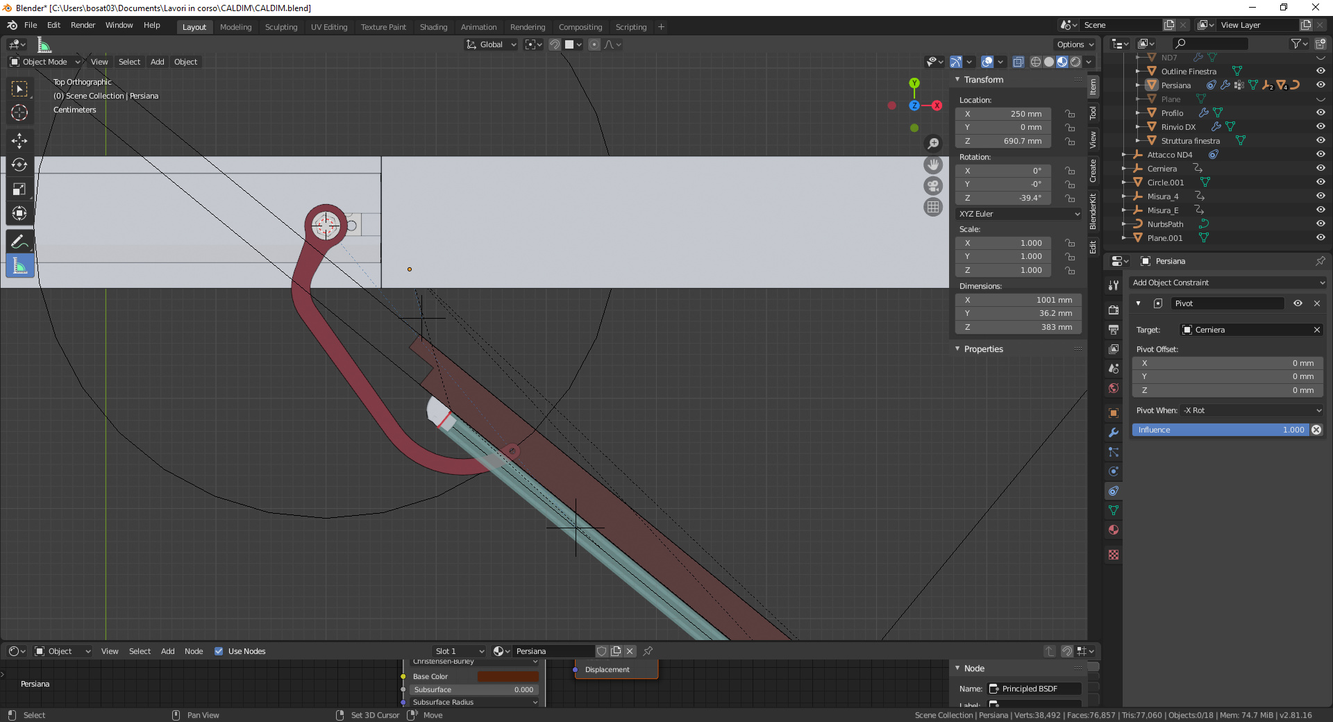
Let me explain how it works. Each arm has its own empty to which it will “Track to”. The arm’s mesh orientation is made so that the local X-axis corresponds to the line joining the centres of the two rotation points (one on the gearbox on the windowsill, the other on the guide), and has the origin on the same X/Y of the gearbox (so that it can rotate around that point).
For each empty, I am calculating the X/Y position based on the intersection between a segment (“Segmento_Guida”) placed on the guide’s centre and parented to it (the guide is parented in turn to the shutter - “Persiana”) and a sphere which centre is on the arm’s origin and which diameter equals the distance between the two centres. Being that everything sits on the same Z, the Z value is not influencing the calculation. This somehow prevents the track-to-empty to slip away along the segment representing the guide when I set up the “Clamp to” constraint.
In the meantime I also managed to create a little GUI on the “N-panel” so that I can collapse the outliner and properties windows to prevent the need to fiddle with custom properties directly (I’m handing over this file to totally non-techie colleagues, so the less interaction they are able to have, the better. In the final version I’ll also prevent them to be able to select the various meshes).
The only thing(s) I’m still not satisfied with are:
the calculation of the empty position lags behind a frame in comparison to the position it should have at frame “x”. While there’s no intention of animating anything, this leads to point 2) which is
upon setting all the quotes, it is necessary to skip one frame forward and one frame back in order for the empty position to be correct. I keyframed the shutter movement so that this leads to a different position between the two frames, and the fact that the movement is eased in and out makes so that the position difference is negligible in those two frames, not interfering too much with the final arm’s position (still it lags behind one frame, but considering that in the first frames there’s little difference between one and the other, it’s no problem).
I’m currently trying to find a way to update driver’s dependencies either through a button (which I would place on the UI) or automagically by skipping one frame forward and one back upon any quote modification. I’ll try to post this question in the proper forum.
I’ll mark your answer as the solution anyway, as its inapplicability only depends on my adversion for armatures rather than being really not applicable.
Disclaimer: I am no programmer at all, the code has been put together using snippets I found on the web and of which I tried to understand the functioning, but that I didn’t write myself (based on some knowledge) so it is more than sure that the code is far from being optimised or elegant. However, it kinda works (except for those two little problems) so I’m ok with it…
Oh and, by the way, how did you get such a clean topology on the arm you used on the hinge? Did you use any automatic retopolgy or re-modeled it from scratch?
I did a basic model from scratch, based off your images, modeling low poly and adding edges. I started with determining the pivot points of the arm and creating low poly circles at those points, then building the rest of the arm from there.

 (except for those two little problems) so I’m ok with it…