Rigging geared joints or: Why not to listen to mechanical engineering instincts

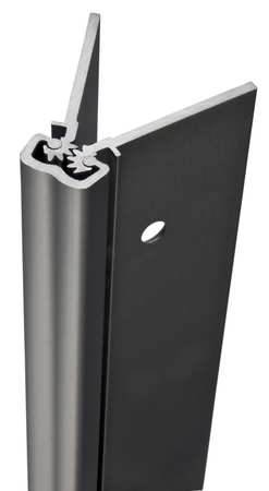
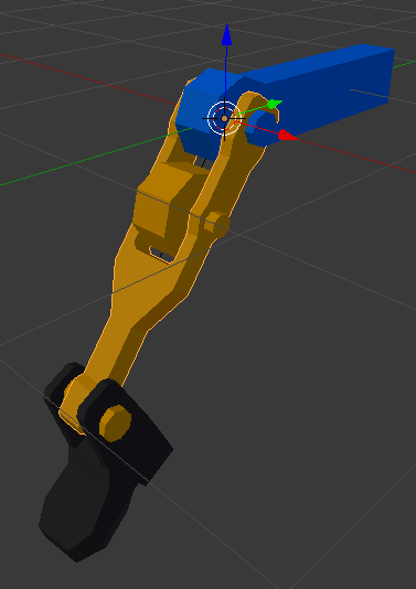
Here’s the problem: I’m attempting to make a segmented knee joint, as seen in the attached file. There’s a gear fixed to the upper leg and a gear fixed to the lower leg; as the knee bends, the gears should not slip or clip into each other.

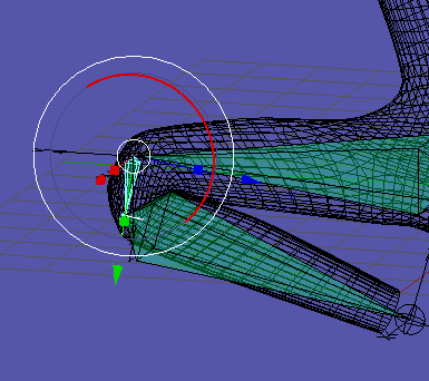
I have attempted to use inverse kinematics to let Blender do this automatically for me, (again, as seen in the attached file,) but it doesn’t even work consistently in the simplest case, let alone in general. To be specific, what worked best in a single case was, once the proper IK limits had been applied, pushing the stiffnesses of the knee and lower leg as high as they would go. Change the situation at all and that no longer works, nor did it even work reliably in the case I described (still visible on the left leg in the attached file.)

Geared Joint Attempt.blend (1.22 MB)

I have considered using drivers, but the problem is this requires the solution of nonlinear equations, which I have not yet done or seen done with single lines of Python code. Here’s a drawing of the situation:

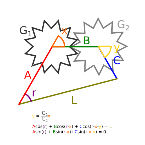
In the above diagram, L is the distance between the “hip” and “ankle” points, A is the length of the upper leg, B the length of the knee, and C the length of the lower leg. G[SUB]1[/SUB] and G[SUB]2[/SUB] are the number of teeth on the gears attached to the upper and lower legs, respectively, (they don’t have to be the same.)
Angles r, x, and y are the variables I mean to solve for, given constants A, B, C, G[SUB]1[/SUB], G[SUB]2[/SUB], and control input L.

Again, this requires the solution of the equations
y - (G[SUB]1[/SUB]/G[SUB]2[/SUB])x = 0
A
cos® + Bcos(r-x) + Ccos(r-x-y) = L
Asin® + Bsin(r-x) + C*cos(r-x-y) = 0

Three equations, three unknowns, two are nonlinear. This is the sort of thing I am under the impression that computers are rather good at.

So how do I do this in Blender?

Don’t try to rig gears using bones. http://cgcookie.com/blender/2009/08/13/animating-a-gear-train/

They’re not a series of gears; they’re geared leg segments, and as such require the ability to be animated with inverse kinematics.

Look at this image; imagine this at a knee joint.

Notice that there is not a single pivot point, but there is a single state possible for a given rotation.

That is the sort of system I am trying to set up, whether it looks like gears are there or not.

You could accomplish that door hinge with a copy rotation constraint on each geared door object.

Indeed that is possible, but look at the problem again.

I have length L, that defines the distance between the hip and ankle joints.

I have a three-segmented leg that must have that distance L between the hip and ankle joints in order for the foot to be in the right place.

I also have well-defined relations between the angles of rotation for each of the three segments.

How do I get [r,x,y] = f(L)?

I do know how to use “copy rotation” constraints - were this a door, I would do that, but a door does not need to have its rotation defined by the distance between the doorknob and the wall (two points on either side of the hinge.)

So forward kinematics of the leg are not the problem here.

(I do thank you for your answers, though. This is the most help I’ve ever gotten!)

Describing your problem using calculus to a bunch of artists is a good way to get a lot of blank stares rather than useful suggestions. That might be why you’re having trouble getting help. I think you may be making this more complicated than it needs to be.

Your description is just confusing, and your .blend file doesn’t make it much clearer. So there are no freely spinning gears in this whole thing? It’s all just fixed gear teeth at the end of leg joints? I’m having trouble envisioning how that would work. What’s moving them?

If, on the other hand, you do have freely spinning gears on a jointed leg, why not just make an IK rig for the leg and use object constraints to control the gears?

Let’s try again.

Basic IK setup.

Look at what happens when the leg bends. The gear teeth pass through each other. They shouldn’t do that. This is the problem I am trying to fix.

Leg2.blend (1.23 MB)

OK, that makes it much easier to see what you’re trying to do. I don’t think you’re ever going to get this to work with IK. It’s just not designed to perform this function.

Try this: make an 2-bone IK leg to control the movement of the leg relative to the foot, but treat those geared leg segments as free gears. Give them copy rotation constraints as if they were spinning on the side of that leg. Make their rotation points controlled by the position of the leg and they’ll have to follow the IK movements even though they aren’t directly controlled by it. I think it will require you to parent the leg segments to empties. That setup should allow you to control the slippage while still manipulating it with a regular IK rig.

I do not understand what you mean by “Make their rotation points controlled by the position of the leg.”

I have included two new attempts based on what I think you might mean.

Leg3.blend (1.59 MB)

On layer 2 in this file are two new leg segments (the red ones) with their rotations controlled directly by a 2-segment IK leg. As you can see, not having their centers of rotation being in the centers of the gear leads to even worse clipping, and isn’t remotely mechanically correct. But I don’t think this is what you meant.

On layer 3 is something that I thought of before and might be closer to what you meant: there’s a 2-segment controller IK leg and a 3-segment skeleton leg (same shape as the leg I used before,) but this time the knee and lower leg bones both use “Copy Rotation” constraints to copy half of the rotation of the lower leg bone. This means that the gears don’t clip into each other, but you can see that the ankle no longer lines up with the foot!

And there’s a way, way more complicated setup that I thought up before that involved a 2-segment IK leg with its leg bones changing length as they bent to keep the gears and ankle where they should be at the same time, but I am certain that this is not what you meant and I fear that this would be just as impossible as what I was trying to do in the first place.

Oh, and that was algebra, not calculus. Bit of trigonometry, too, but not calculus. Believe me, I’ve wanted calculus-related features, such as the ability to keyframe velocity instead of position, but I think that would require a horrific rewrite of Blender’s very animation system itself. And I have also - no joke - wished I could use Blender to render in non-Euclidian space.

… Boy, maybe I’m not cut out to be an artist after all.

Just skimmed thru this a bit and if your not using drivers because the solution is more than a 1 line equation, then you should look to pydrivers. I have not personally used them, so take that into consideration. But it’s my understanding that you write a python function that contains your formulas and it’s used to evaluate the driver. Here’s a link to the manual page about them:
http://wiki.blender.org/index.php/Doc:2.6/Manual/Animation/Editors/Graph/Drivers#The_pydrivers.py_Blender_text
Not many users use them, so finding good examples of how to use them might be hard to find.

Randy

I will look into that. I know there are ways to solve nonlinear equations with Python (involving fsolve, for example,) but I did not know how I would implement them. This may be just what I need, thank you.

I don’t think your bone layout is right.

If you actually layout the thing, you start to see how each gears will need to be connected. Upper gear is fixed to the thigh. When you drive the lower gear, the leg rotate from knee joint. It’s a two-bone joint. Not three bone as you have it:

http://i1135.photobucket.com/albums/m626/cabby24/Blender%20Pics%202013/gearlg_zps00864905.png

Ridix’s solution looks pretty close to what I was envisioning. In your layout I can’t even figure out how that leg would work. You just have some gear teeth, but what is driving them? What, for that matter, is even holding them together? Not in a rigging sense; I mean if you just looked at that thing rendered without the bones visible, what is making that work?

With the layout Ridix shows, you have one free-spinning gear that could conceivably drive the knee joint. In rigging that, the gear in the tibia area can be driven by the leg’s movement, rather than directly by an IK chain.

I know. And I knew you’d call me out on it. I was taking artistic license and using hyperbole to make the point. :stuck_out_tongue:

Me too. Mostly for Lovecraftian purposes.

Edit: I’ve also spent the last half hour digging up an old steampunk robot I made years ago with a geared leg similar to what you’re working toward. It even has a joint where one segment of the leg ends in gear teeth. Heck, it has parts that are actually driven by gears rather than bone chains. The arms extend on a gear-toothed rail with a chain system operated by a driver bone. Why? Because screw you, Guy Who Has To Animate This Thing. :RocknRoll: I figured I’d just give it to you and let you cannibalize it for whatever parts you like. Unfortunately the most recent version I can find now is from very early in the rigging process. The only thing rigged is a series of pistons in his abdomen. The fully rigged version must still be around here somewhere.

And that’s a much easier configuration than what I am trying to make.

Here’s something that (I hope) should make the design clearer.

Leg4.blend (1.43 MB)

Physically, if this were a real machine, the purple gear drives the grey knee segment, which makes the blue lower leg segment rotate twice as fast as it itself does, via the geared junction between the upper and lower leg sections. Again, if this were rigged via FK alone, this would be perfectly, wonderfully easy. But with IK…

This is inspired by the anatomy of the human knee: http://kneeinjuryinfo.com/wp-content/uploads/2011/06/knee_anatomy.jpg. You will notice that, in the knee, there is indeed no single point of rotation (like there is in Ridix’s leg) between the primary upper and lower leg segments.

This has another effect: the lower leg segment can turn 180 degrees with respect to the upper leg segment without clipping into the upper leg. If you make a human character without a knee-segment bone in the armature, you will run into that problem. But if you do this:


it looks more realistic.
Now that works with plain ol’ IK! It doesn’t matter that the knee bone’s local rotation be exactly the lower leg bone’s local rotation. But I had the increasingly clearly foolish idea to try to apply this design to a machine, just to see if I could!

Ya, making realistic knee movement is not easy. The knee joint is a rolling / sliding joint. Over all effect of joint do seem rotation from a pivot though as you can see here:

It’s true it’s not exactly right - one thing I know is that my example non-mechanical joint has a knee segment that is much too long, but that was just a proof-of-concept.

Anyway, I do believe I have my answer - If I can figure out how to install Scipy, I should be able to set up a driver that can solve those equations, and so create an IK setup without using any of Blender’s IK constraints for this purpose. I’ll find out later if the numerical equation solver interacts well with drivers, as that is my next point of concern.

But thank you all for your help; I’m sorry to put you all to such trouble for what was an idle experiment more than anything else!

Let me apologize for contributing to topic drift first. Sorry. But by combining Solvent’s knee rig with what I see going on in ridix’s video, I had an idea for what might be an even better knee rig. It probably doesn’t help your robot, Solvent, but actually it looks to me like you’ve got the gear slippage pretty much fixed.

So that being said, check this out:KneeRig.blend (488 KB)

The bone named Thigh does the mesh deforming that the top bone in the IK chain (named Femur in this example) normally would. But with Solvent’s clever third bone in the knee to simulate the sliding of the tibia over the head of the femur, it should keep the knee’s shape in the front slightly better than Solvent’s, while still taking advantage of the improved bending in the back.

Don’t apologize, Solvent. This was a cool set of experiments. And I need to test my new knee out to see if it’s as useful as I think it will be.

your problem apears to be on of mechanics rather than math.

your trying to use an offset gear to pivot a second set of gears around each other. thats not going to work as the offset gear (the pink one driving the grey link) is trying to swing the lower leg around the fulcrum of the link gear. the upper leg knee cog is getting in the way of thiss and if the model were to be real the teeth on the upper knee would simply cause the gears to seize. worst case, you would shear the pink gear from its drive shaft. doing this with bones is going to take some re thinking of the entire system. let me experiment

Small Troll:

I think it’s physically possible. Here’s a setup animated with FK to show that there is no slippage or seizing of the gears when the knee rotates a full 200 degrees (yes it’s clear that there’s clipping when the hip/ankle collide; ignore that, suppose rotation is limited to where that wouldn’t happen in a physical setup!)

Leg5.blend (1.43 MB)

(Also note how easy it is to do this with FK.)

I admit I have not tested the mechanics. No sooner than Thursday, I could whip up a LEGO version of this to make sure there’s nothing physically wrong with it, if anyone really wants that. It may not be the wisest configuration from a design/structural perspective, but that’s where my character designer instincts override my mechanical engineering ones: it just looks cool!

… It looks cool to me, at least!

hmm ok it does look like it could work but i think this is one of those situations where IK is innapropriate. the gear in the knee joint is influenced by the rotation so when the lower leg swings the gear is what causes it to pivot. an ik wants to pivot the joint directly at the bone hinge which will always cause slippage and the appearance that the joint should seize. FK is the way to go with this, you will just need to tweak the inbetween frames to avoid the gear teeth from clipping. this will take a bit of time to animate fully :smiley: