@pafurijaz - thank you, I do my best 
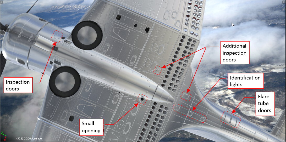
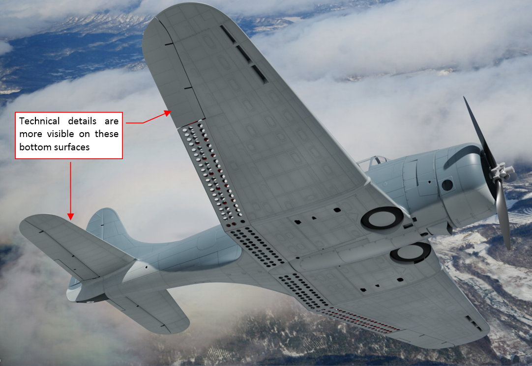
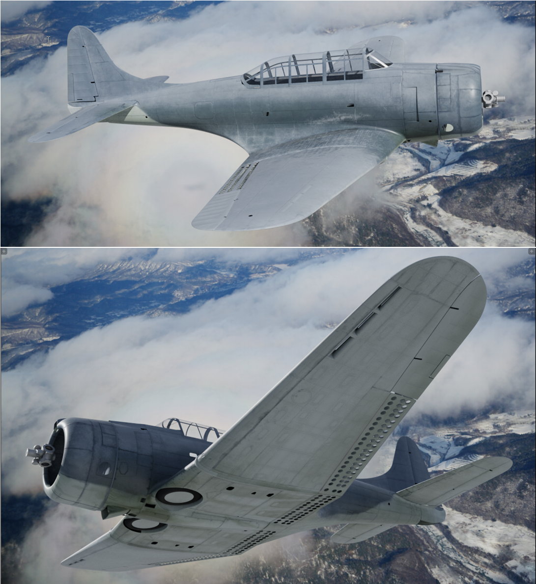
Although the technical details of aircraft skin are symmetric in general, there are always exceptions. For example, look at the bottom surfaces of the SBD (Figure below shows them on my model):
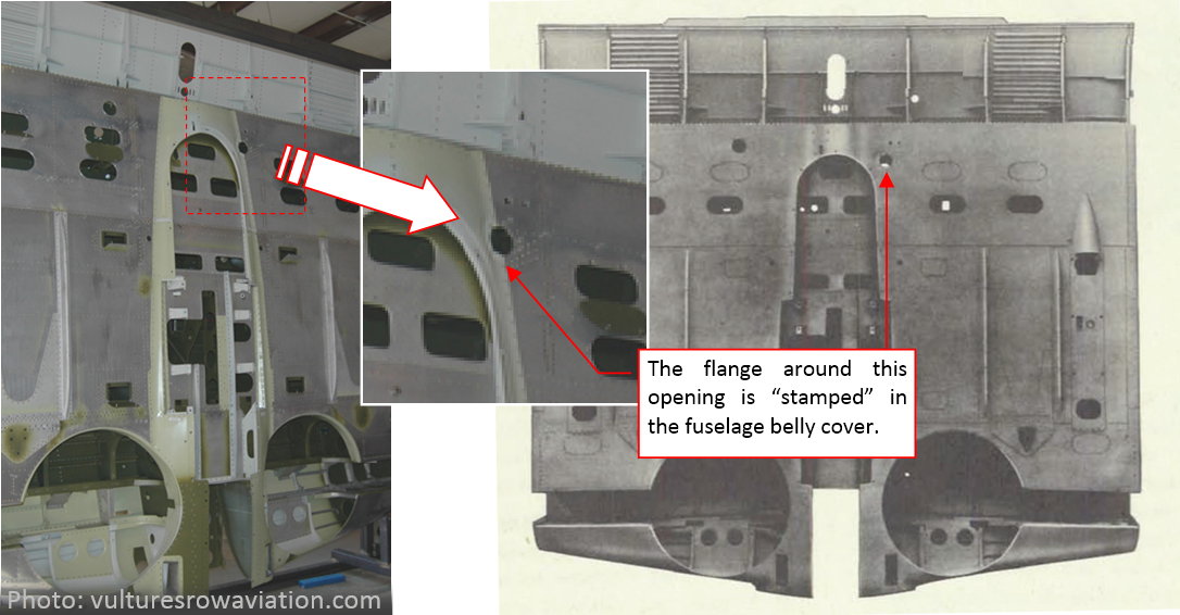
As you can see, there are several details that are not symmetric. (In addition, let’s do not forget about the asymmetric opening under bottom covers of the fuselage, visible on this picture – see Figure 70‑9 in my previous post).
So far I mapped only the symmetric half of the wing on the UVTech texture layout. It occupies a significant portion of the space. Such a size allowed me to draw all the technical details in higher resolution. The plan was that both wings will be mapped in the same points of the UV space, because most of their structure is symmetric. For the few asymmetric details, I was going to prepare additional areas, intended for the UV mesh faces that contain these elements.
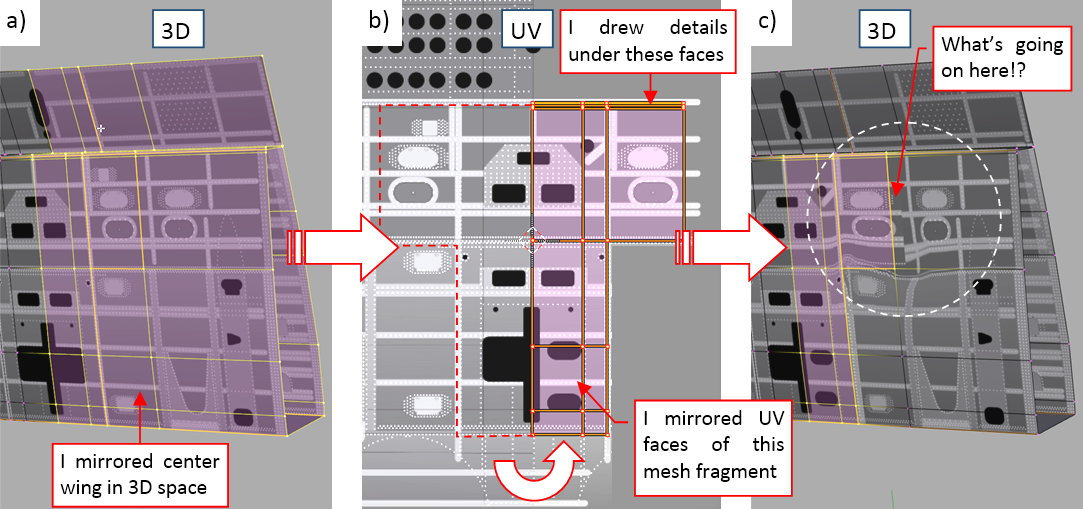
Let’s see how it works in practice. I created the right side of the center wing by mirroring its left side (see figure “a”, below). Initially, the texture image is symmetric, because mesh faces from both sides are mapped onto the same areas in the UV space:
Then I drew the asymmetric elements of the center wing on the image, and “flipped” an L-shaped selection of the corresponding UV faces onto this area (figure “b”, above). However, when I looked at the effect in the 3D space, I saw a huge texture deformation (figure “c”, above). Why did it occurr?
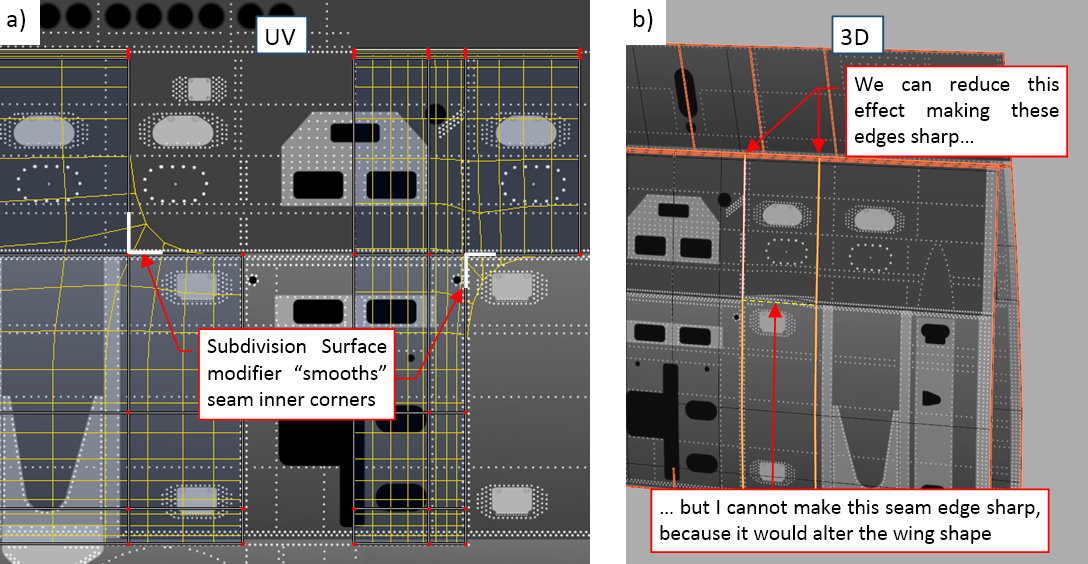
The reason of this deformation is the Subdivision Surface modifier that I used to smooth this mesh (as well as most of the other meshes in this model). To preserve proportions of the texture image, I enabled its Subdivide UVs option. When I turned on in the UV/Image Editor the preview of the modified (ultimate) UV faces, I saw the pattern as in figure “a”, below):
Edges of the ultimate, subdivided UV mesh faces are marked in yellow. As you can see, the Subdivide UVs option “smooths” all inner corners of the original UV layout! Well, I cannot disable this option, ibecause it would deform the texture details, on all mesh faces. Still, it is possible to counter this “inner corner” effect by sharping selected seam edges (i.e. by increasing their Crease coefficent to 1.0). As you can see in figure “b”, above), I was able to fix most of the original deformation in this way. However, while I could mark as sharp any of the “rib” edges, I could not do the same for the perpendicular “stringer” edge, because it would change the wing shape. (It would alter the side view profile of the center wing).
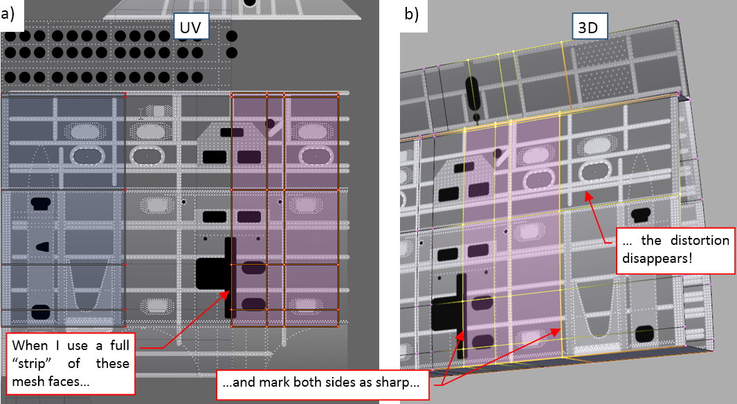
All in all, the solution for the wings was to “cut out” from their UV layout “stripes” of the faces that span across whole wing chord. Such a stripe has no inner corners (figure “a”, below):
As you can see in figure “b”, above, it produces the desired effect. The drawback is that it occupies more precious UV space, and I had to replicate more details on this drawing (for the whole span of such a “stripe”).
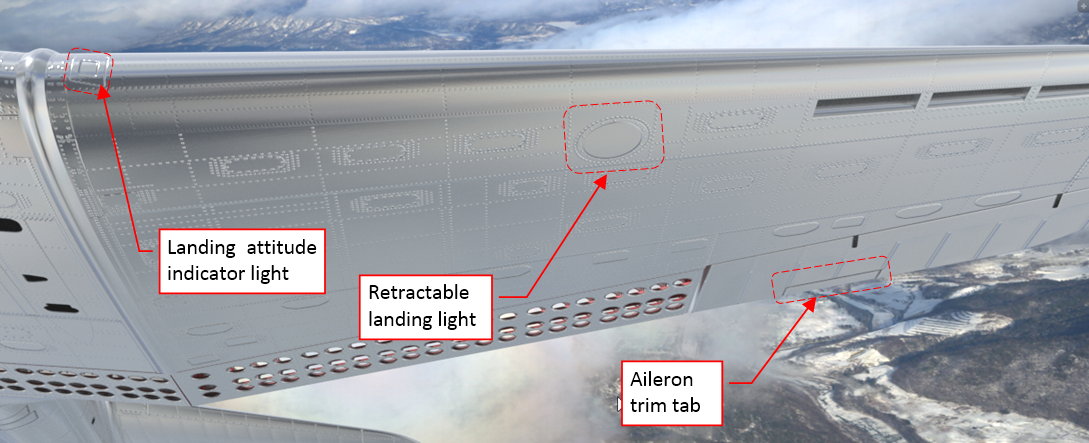
There are also few differences between the left and the right outer wing:
Strangely enough, aircraft designers usually place all additional stuff like the aileron tab or landing light on the left wing. At this moment I just marked on the wing the contours of these two lights. During the next, “detailing” phase of this project, I will create all of these three details shown in the figure above as separate objects. However, I still have to modify the bump map texture, because of the different rivet pattern around these lights and frame around aileron trim tab. (When there is an element without influence on the rivets/panels pattern, I skip it at this moment. For example: in the left leading edge of the center wing there is small round inlet of the cockpit ventilation air. It does not alter the rivet seams, thus I will recreate it completely during the detailed phase).
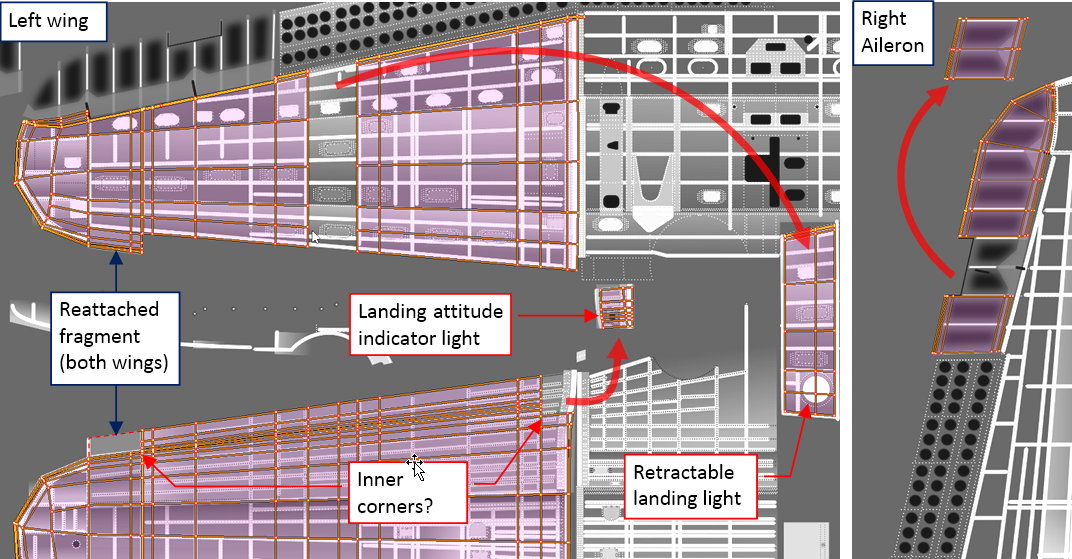
Following the experiences with the UV mapping of the center wing, I stripped two full-span bands of the UV faces from the left wing and the right aileron:
Frankly speaking, drawing details of these additional strips in a way that they seamlessly fit the rest of the wing was quite difficult. As you can see, I also made small adjustment on the leading edge seam, on both wings. (It removed the deformation described some time ago in this post, Figure 64-9).
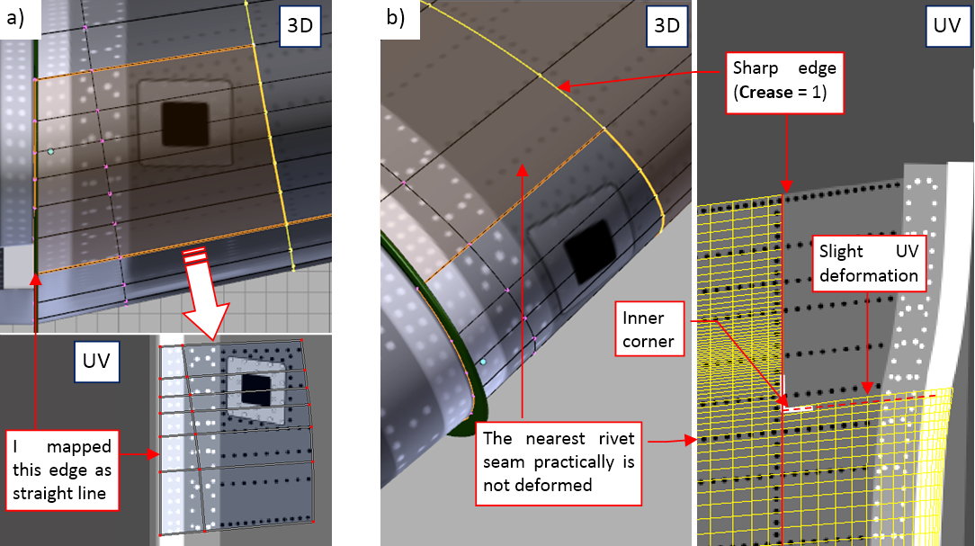
The UV layout depicted above contains three inner corners, all located on the leading edge. This is a kind of a compromise: I used sharp “rib” edges (Crease = 1.0) to minimize the overall deformation of the mesh UV faces around these points. They still bend the texture along their “stringer” edges (as in the case of the center wing, depicted previously in this post). However, in these two particular cases I managed to “hide” this unwanted effect. Figures below show how I did such a thing:
Figure “a”, above, shows the fragment around the landing attitude light indicator and its faces in the UV space. This is a simple quad, without inner corners. As you can see, I mapped the inner wing edge as a straight line, to facilitate drawing of the multiple rivets and panel seams that run along it. Figure “b”, above, shows the details of the corresponding inner corner in the main part of the mesh. I used a sharp “rib” edge along this seam. Still there is deformation along the perpendicular “stringer” seams, but it is practically invisible. There are two factors that “hide” it:
- The edges adjacent to the seam edge are relatively close to each other, which minimizes the deformation size;
- The seam edge runs in “safe” distance between nearest visible element of the texture image (a rivet seam), so the deformation in the UV mapping disappears before it reaches this image;
The possibility to “cut out” such a small part from the main body of the UV faces preserved precious UV space. It also allowed me to avoid duplicating on the texture picture of all the details along the inner edge of the left wing. (It would require a few hours, to fit such a separate fragment to the rest of the picture).
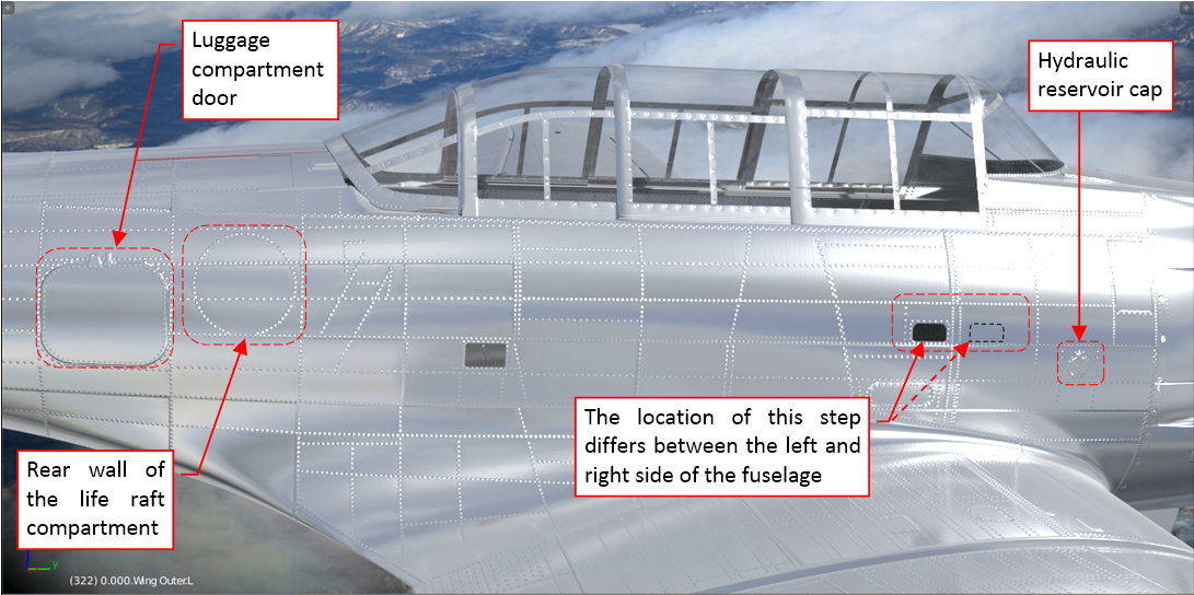
Apart the differences on the bottom of the fuselage, depicted in the first figure of this post, there are also differences between its left and right side:
The circular door of the life raft compartment was located on the port side (you can see it in the last picture from the previous post - Figure 70‑10). The raft was packed in a tube riveted to the starboard skin, creating characteristic circular rivet pattern (visible in the figure above). The door to the baggage compartment was also located on the starboard. There were also differences in the locations of the steps to pilot’s cockpit.
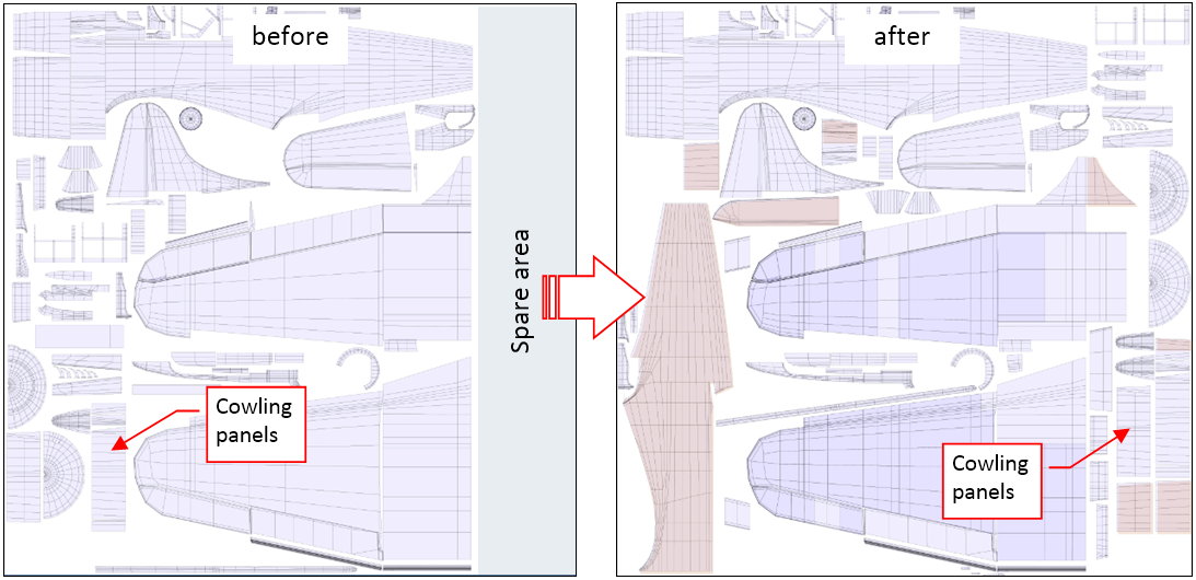
The shape of this fuselage is much more complex than the wing. I cannot mark any of its edges as sharp, because it would change the shape of this element. Thus, after the experiences with the wing, I decided that I need to map in the UV space the whole fuselage right side. Fortunately, I preserved some spare space on the original UVTech layout. Now I used it to fit this part:
On the picture above, I marked the newly added objects in orange. The main dilemma was how to fit another fuselage silhouette by replacing as few drawing elements as possible. As you can see, I finally decided to “shuffle” the cowling panels from the left side of the original image into the spare area. It created enough space for the fuselage on the left. Note that I also added the right sides of the cowling panels (because they also were asymmetric: there were two inspection doors on the left side of the cowling).
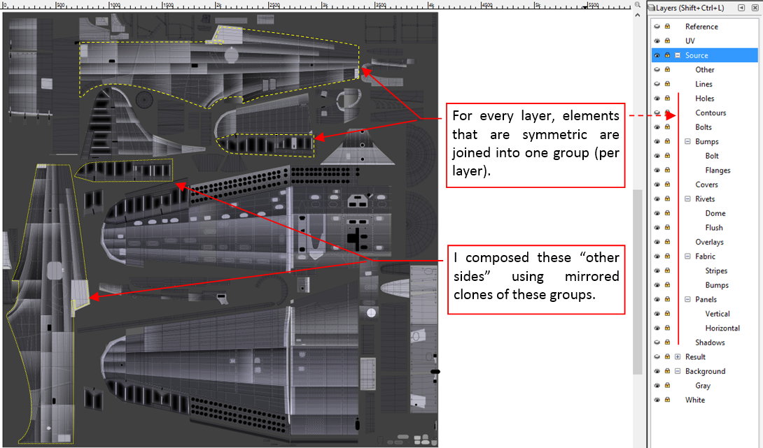
Figure below shows the source image of the bump textures adapted to this new layout:
My experience tells me that in the future I will have to update some details of this picture, following new findings in the photo material (it is just a matter of time). Avoiding applying the same modification twice, I decided to join into a group all the originally drawn elements that are identical for both sides of the fuselage and belong to the same layer. Then I created a mirrored clone of such a group and placed it over the right side of the fuselage. After I “filled” this contour with all the required clones, I drew the asymmetric details. In the future, when I change contents of any of these groups on the fuselage port side, they will be automatically updated on the starboard.
I drew the other side of the elevator in the same way. In this case, the whole difference is a plate mounted between two ribs. It contains the hole for the trim tab actuator. Of course, I could “cut out” this very mesh fragment, as I did in the case of the aileron. However, in the SBD the elevator is smaller than the aileron, thus I decided to make the “full size” copy of its opposite side. (Just to make the eventual future modifications easier).
In this source *.blend file you can evaluate yourself the current version of the model, and here is the sourceInkscape file of its textures.
This is still as fascinating as ever. You could probably build a real one with less work.
About the extra bits going on the left wing: it’s probably just a convention, so that anyone will know where to find them when doing maintenance.
Thank you!
Nevertheless, drawing a dotted line (which Cycles transforms into rivet seam) is still much easier than drilling holes for each of these rivets :).
This post is a small digression about a modeling technique that you may find useful.
There is a detail on the bottom surfaces of the SBD center wing: an opening, made partially in the cover of the fuselage belly:
The difficult part of this detail is its flange, stamped in the fuselage cover. I just have two photos of this element, both of average resolution. On both of them you can see a typical circular recession, made around the opening in the belly cover. In fact, such a feature is quite common in the sheet metal design (you can see plenty of such stamped flanges in various places inside your car). This is a minor detail, too small for any serious modeling, but too large for recreating it with the textures.
I had an idea of shaping this recession using so-called displacement modifier. (I used it for a certain purposes in my previous model). It displaces mesh faces along given direction, on the distance determined by the color intensity of assigned texture. (That’s why I waited with this detail for the texturing phase). The displacement modifier requires plenty of small mesh faces. I thought that I will generate them by increasing the number of mesh subdivisions in the Subdivision Surface modifier assigned to this cover. Preparing for this, I split the mesh of bottom fuselage in the middle. This operation created two objects, representing the forward and rear part of the Dauntless “bomb bay”. I was going to increase the subdivision level in the rear part, which contains the flange.
However, after initial trials I went to the conclusion that the displacement modifier is not optimal solution for such a circular shape with rounded edges. It would require relatively high subdivision level, to obtain this shape with appropriate precision. (It would generate hundreds thousands of additional elementary faces). Too much troubles for such a small detail. Thus I decided to find another method that requires less resources.
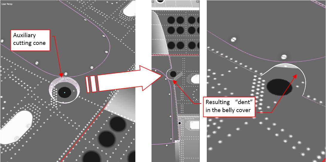
Finally I modeled it using a technique that resembles me methods used by dentists. First I cut out in the belly cover circular area around the flange:
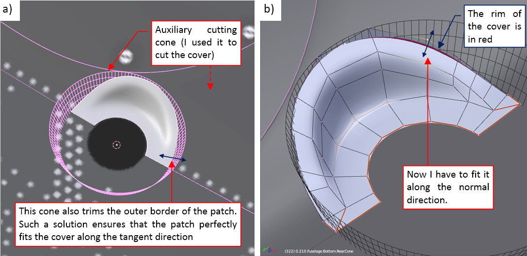
To not complicate the mesh of this cover, I did it dynamically, using additional Boolean modifier and an auxiliary cone (the latter as the “cutting tool”).
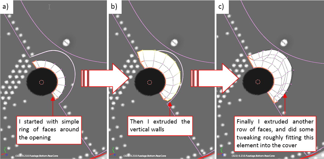
Then I formed around the opening a small ring of faces, and extruded them, creating the basic shape of the flange:
In the next step, I trimmed the extent of this mesh faces using the Boolean modifier and the same auxiliary cone that I used for the belly cover. Then I fitted external edges of this flange to the edges of the belly cover:
Note that, thanks to the Boolean modifiers, I only had to fit these edges along the normal direction of the joined surfaces. It required less work. To further facilitate this task, I assigned a contrasting red color to the rim of the belly cover.
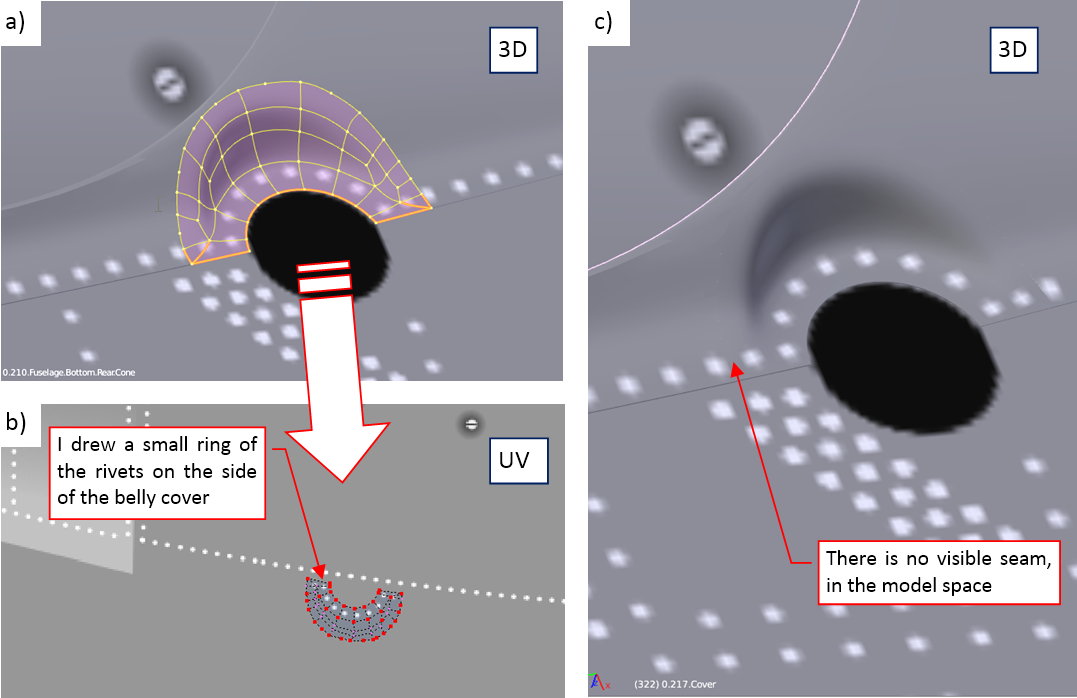
Finally I mapped this small detail on the general UV map (figures “a”, “b” below):
The UV map of this patch is a simple projection from the vertical view. So far it looks good – there are no visible seams between the patch and the belly cover (figure “c”, above).
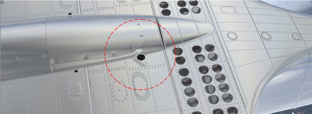
Figure below shows the final result on the rendered picture:
You cannot recognize here that this fuselage cover is created from two separated objects – it looks like a single one. This is the effect I wanted to achieve.
Of course, this method of using shared Boolean “tool” for trimming both involved objects is useful for modeling single features stamped in a sheet metal. It would require too much work for modeling more than two or three such objects. (Fortunately, they do not occur too often).
You can examine the details of this mesh in this source *.blend file (this the same file that I attached to the previous post).
I already finished the bump map (in the second-last post), so it’s time to introduce another texture: the reflection (ref) map. It alters the basic reflectivity (gloss) assigned to the material. In addition, it also alters the material “roughness”. (In the typical CG materials the roughness and reflectivity are coupled in an inverse proportion). These two parameters are important, when you have to paint an oil streak or a soot streak. Both are black – the difference between them lies in their reflectivity.
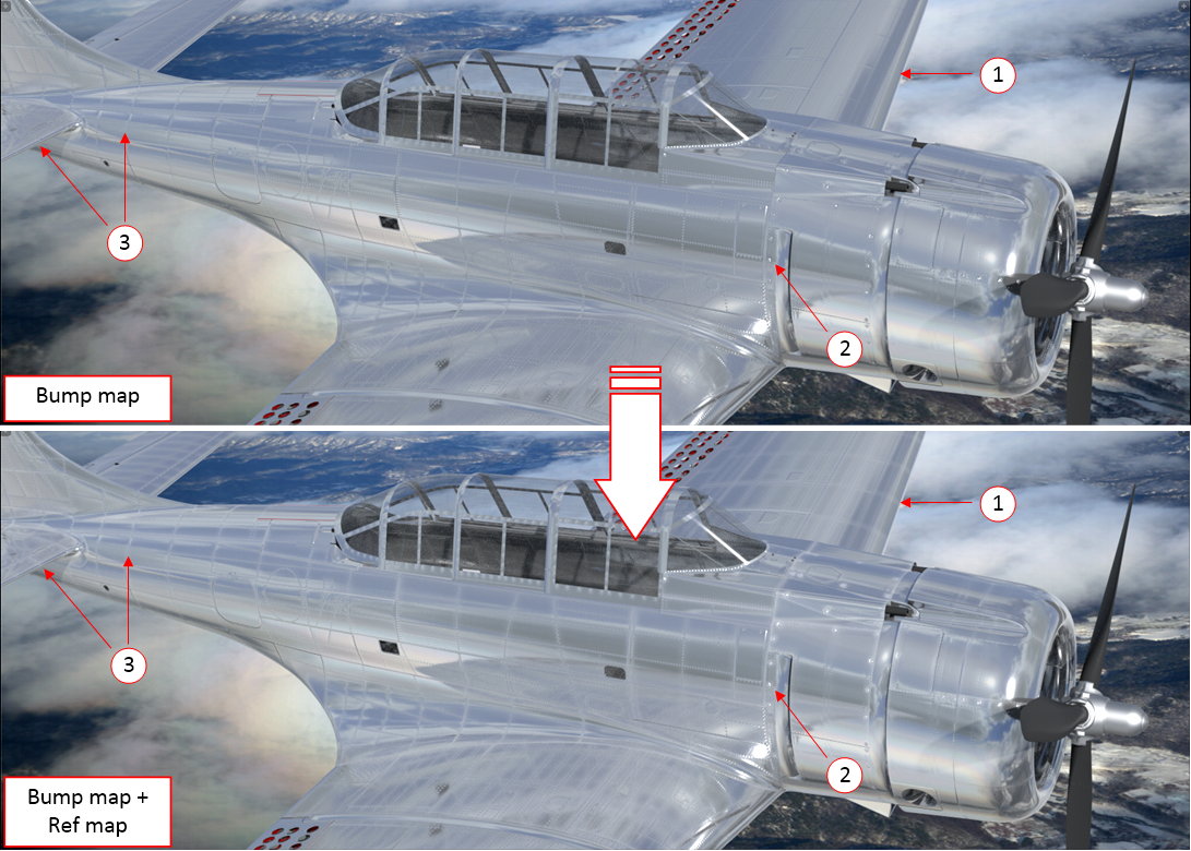
The effects of the ref map are most visible inside these areas of the model that actually reflect the light:
Figure above shows two renders of the same model: the upper one was created without any reflectivity map, the lower one uses a basic ref map. (I created this texture around the technical details of the aircraft skin).
Compare the rivets seams in these two pictures, especially in areas (1) and (3). As you can see, ref map “emphasizes” these elements. In the lower picture the rivets and panel seams look more weathered than in the upper picture. The same applies to the bolts (2). In general, I use the reflectivity map to recreate the weathering and dirt that accumulates on the aircraft. Of course, the dirt pattern of this texture has to be tightly coupled with the corresponding pattern on the color map. (I will describe it in the next post).
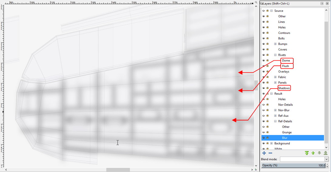
I composed the basic reflectivity map in Inkscape, using three overlapped pictures. I briefly describe this composition below, on a representative fragment of the texture: the wing tip. (This fragment is small enough to make visible the minor details of this image. You can also examine the source Inkscape file for the further details). The first component of this texture is a blurred image of the basic rivet seams:
It contains clones of three source layers: Rivets: Dome (turned black), Rivets:Flush, and Shadows. To alter the color of the Rivets: Dome layer clone to black, I used an auxiliary SVG filter that contains just a single ColorMatrix component. Similarly, to blur the contents of this Ref-Details:Blur layer, I used another SVG filter, that contains a GaussianBlur component.
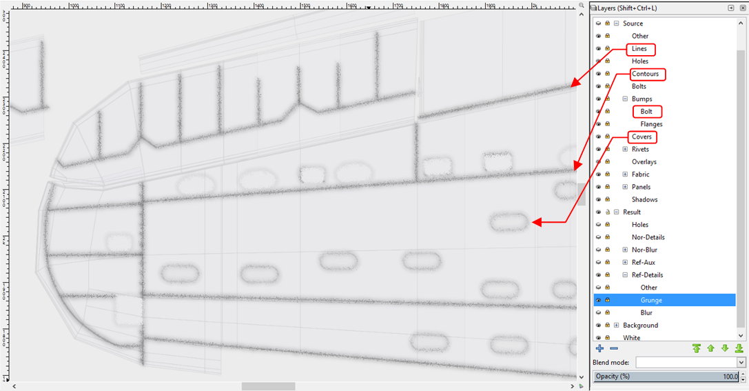
The other component of this texture emulates the small, random dirt and scratches that accumulate around all seams. I named it Grunge:
I composed this picture from clones of the Lines, Contours, Bumps:Bolt and Covers layers. Their contents is “dispersed” here using a special SVG filter. (For details of this solution, see “Virtual Airplane” guide, chapter about Inkscape, section about the dirt effect). I used here a new layer Contours, which I have not mentioned in previous posts. It contains just outer outlines of some selected elements (for example – cowling panels), drawn using thicker black line. (Such a line adds additional dirt along their edges).
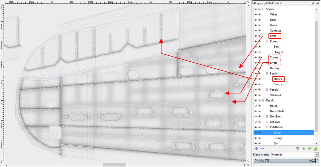
I placed the dirt image (Ref-Details:Grunge layer) over the blurred panel lines (Ref-Details:Blur layer), and placed on top of them another layer named Ref-Details:Other. It contains clones of the Rivets, Fabric:Stripes, Covers, and Bolts layers. The idea is that this layer “clears the dirt” off the protruding skin elements (that’s why the clone of originally black Rivets:Flush layer is white here). Figure below shows the final composition of the Ref-Details texture:
The basic elements of this image – clones of the source layers – will update automatically, when I change one of the original layers. This feature is important for me, because I often have to introduce small corrections to the model, even during the last, detailing phase of the project. (You never know, when you find a new picture or drawing, which reveals that a particular detail in your aircraft had a different shape). Some of these corrections require corresponding changes in the textures. The automatic update of the three basic textures (two bump maps, and this reflectivity map) is a great help in such a case.
I exported contents of the Ref-Details layer into a file named ref_details.png, and connected it to the material scheme:
Because this Inkscape image re-uses the same components as in the bump maps, the reflectivity texture uses the same UV layout (UVTech). I connected this texture to two sockets: Ref Image and Dirt Image. The max. (i.e. basic) reflectivity is controlled by the Reflectivity parameter, while the contents of the ref texture decreases this value locally, in appropriate areas. The intensity of this effect is controlled by the Range parameter in the auxiliary Range To Max control node. To control the dirt effect I use the Dirt Intensity parameter (there is no need for another Range To Max control node on this line, because the basic Dirt Intensity = 0). (For explanation of the inner details of the X.Textured Skin group, see “Virtual Airplane” guide, chapter “Texturing the Model”, section “Summary”).
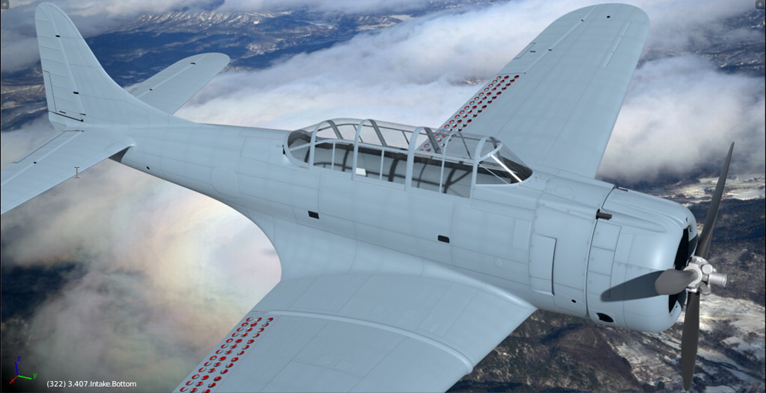
The dirt is hardly visible on the metal surface kept in the “natural finish”. (You can see the effect of this reflectivity map on such a surface in the first figure in this post). Om this example I switched the material to the non-specular Navy Blue-Gray color (see figure above). The U.S. Navy and Marines used this color to paint the upper and side surfaces of their aircraft in 1941, 1942 and 1943. This is just the first approximation – a solid color for all surfaces. (I will create the proper color texture in the next post).
Figure below shows the result of applying the reflectivity/dirt map (connected as in figure above) to a low-specular surface:
Still, the aircraft depicted in the figure above seems “too clean”.
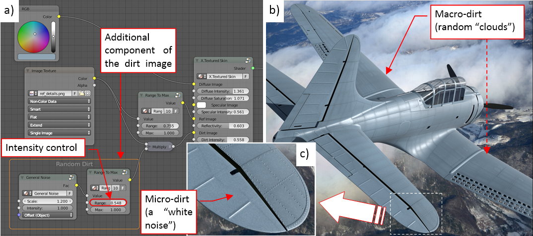
To further enhance this dirt pattern, I combined the original image with a random “noise” pattern (see figure “a”, below). This random pattern is composed from two different Noise Texture nodes of different size. One of them creates big darker and lighter “clouds”. I set the intensity of the General Noise texture (in the accompanying Range To Max node) so that its darker “clouds” have similar shade to the elements of the of the ref_details.png image. It makes the resulting dirt/ref pattern less regular (see figure “b”, below):
The other component of the General Noise pattern creates a “white noise” of small darker and lighter spots (see figure “c”, above). It resembles the real micro-dirt, dispersed evenly on the whole aircraft surface.
Continued in the next post (the original post was longer than 10 000 characters)…
Continuation of the previous post:
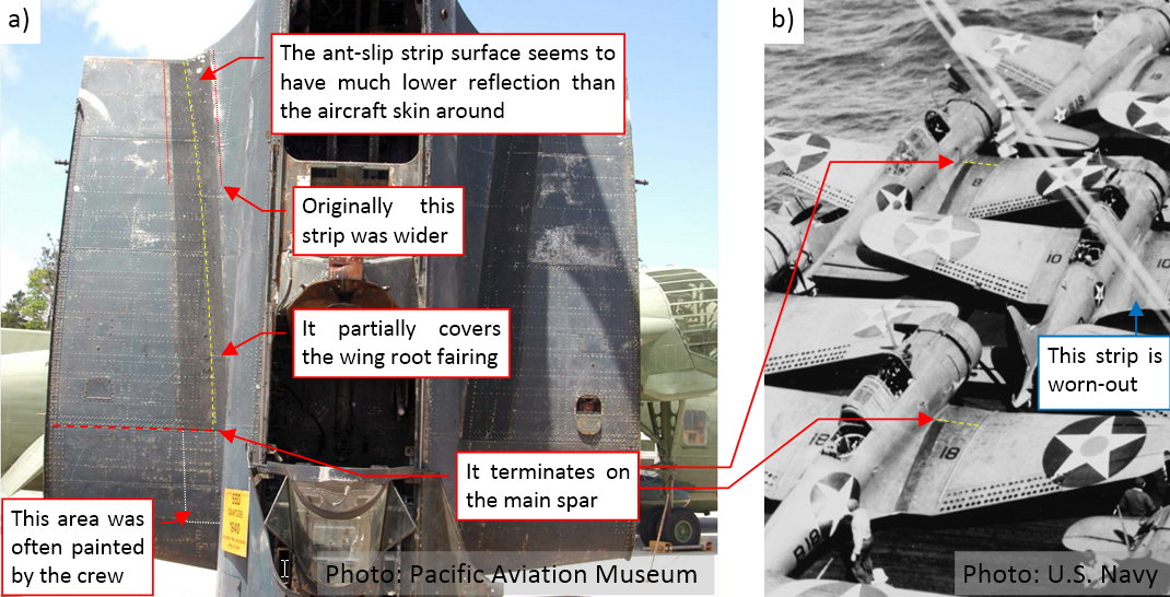
On all SBDs you can see anti-slip stripes running along both sides of their fuselages. Its surface was painted in the factory with a special “rough” paint. It seems to have much lower light reflection than the rest of the aircraft surface. I will recreate this reduced reflectivity of this strip on the ref texture, while I will paint it in black later, on the color texture.
It seems that the anti-slip strip is longer on the restored aircraft than on the photos of the original SBDs. To determine its true (i.e. original) size and location, I used the archival photos, as well as the contemporary photos of the few SBD wrecks (taken before their reconstruction). Below you can see two of these photos:
Figure “a”, above, shows the original state of the SBD-5 restored by the Pacific Aviation Museum, while figure “b”, above, shows the SBD-3s on the deck of USS “Enterprise”, on April 4[SUP]th[/SUP], 1942. It is a good photo, because it shows multiple aircraft belonging to the same squadron. You can see on these bombers that the anti-slip stripes extend from the trailing edge to the main spar of the wing. Precisely the same span you can see in the original SBD-5 from figure “a”, above. However, on some airplanes that I saw on the photos the anti-slip strip is extended over the main spar, into the area that I marked in figure “a” with white outline. I suppose that this forward part of the strip could be painted in black by the local crews. It seems that they used various paints for this purpose, sometimes even the glossy ones.
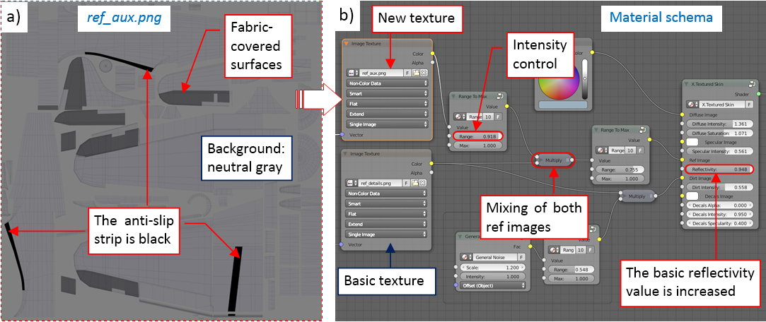
At this moment I recreated this strip in its standard shape: from the trailing edge to the main spar. For this (and other, similar) purpose I made an auxiliary reflectivity map, and named it ref_aux.png (see figure “a”, below):
You can see that I drew the anti-slip stripe in black there – this means that this area will have the minimal reflectivity (and maximum roughness). Thinking about the eventual glossy fragment at the end of this strip, as well as the oil streaks that I will paint in the next post, I set its background color to neutral gray (50% black). All the glossy elements will be lighter than this color. In addition to the strip, I decided to decrease the reflectivity of the fabric-covered control surfaces. (The fabric surface is rougher the metal surface, even when you paint them using the same paint). Because this difference in material reflectivity is not as intensive as on the anti-slip strip, I filled the aileron, elevator and rudder outlines with a dark gray instead of black.
Figure “b”, above, shows that I mixed these auxiliary and basic ref maps using a Multiple node. This means, that now the background color of the resulting image is close to the neutral gray (it was 92% white, before). To compensate this difference, I had to increase the basic Reflectivity (the parameter in the X.Textured Skin group) to the maximum.
Below you can see the results of applying this additional ref map:
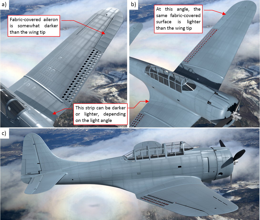
In figure “a”, above, you can clearly see the anti-slip strip as a dark area on the center wing. Similarly, the fabric-covered aileron is also somewhat darker than the rest of the wing tip surface. However, this effect depends on the incoming light angle. When you look at this model from the opposite direction (as in figure “b”, above), you will notice that these areas are lighter! In the real world, you can find the same effect on the photos of the aircraft painted with non-specular paints.
Figure “c”, above, shows the final effect of the reflectivity maps, created in this post. In fact, this is just a beginning: this texture represents an “overall dirt”, evenly dispersed on the whole aircraft. Now I have to add the soot and oil streaks that appear on every real piston-engine airplane. The radial R-1820 engine (and especially its exhaust stacks) provided plenty of interesting patterns on the SBDs fuselages and center wings. However, I want to paint this dirt simultaneously on the reflectivity map and the color map. Thus in the next post I will prepare the basic color (diffuse) texture, then we will return to the “dirt painting”.
In this source *.blend file you can evaluate yourself the current version of the model, and here is the sourceInkscape file of its text
Just WOW.
Stunning work.
@thorst: thank you for following!
Today I will start the diffuse map:
The color (also known as “diffuse”) map is the most obvious texture, which you can find on every model for games. In my models it is composed of three separate images: the camouflage, the dirt (stains, soot, etc.), and the markings (national insignia, tactical numbers, warning labels, and all other similar stuff). In this post I will compose the basic camouflage texture.
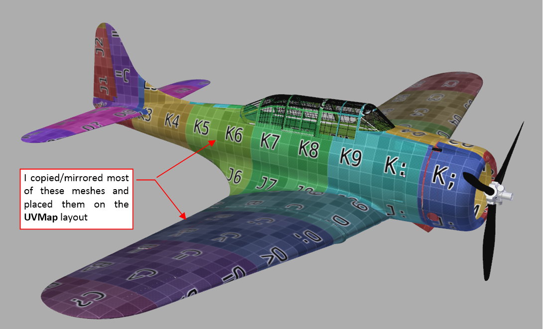
Some time ago I unwrapped the left side of this model (see this post, Figure 62-3). Now I had to complete this work, creating remaining elements of the right side, and unwrapping them on the UVMap layout. The final result looks like the model in the figure below:
For the precise mapping, I used here the color grid image, which I already used in my previous posts. Note the different square colors on the left and right wing, as well as the different letters on the right and the left tailplane.
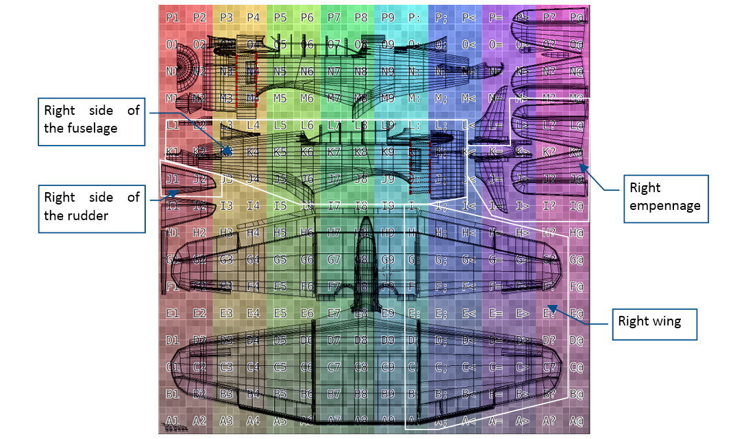
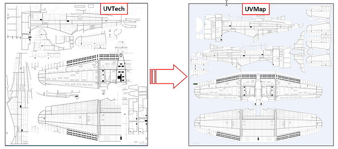
The complete UVMap layout looks like in the figure below:
In this layout the areas occupied by each mesh are smaller than in the alternative UVTech map. However, while in the UVTech layout both wings and the tailplane are represented by their left sides, in the UVMap layout each of them has a separate place. However, some elements are intentionally placed over another. For example – the inner walls of the “letterbox” wing slats. In this layout I unwrapped their upper faces over the wing upper surface, while the remaining faces partially “touch” the wing lower surface. (In this way I ensured, that the color of these less visible elements will match the surface around them). There are some other elements, placed over the wing or fuselage in this UV layout.
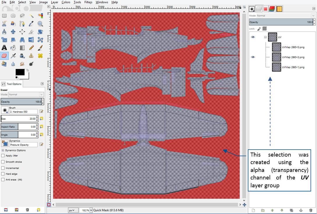
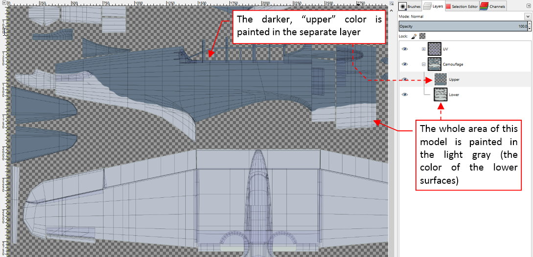
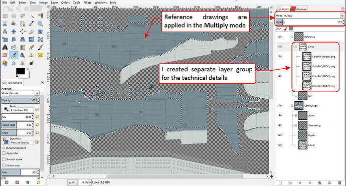
I will paint the camouflage and dirt textures for this model in GIMP. First I imported the UVMap layout from Bleder, and used it as the reference picture:
Note that I have a separate UV layout for each SBD version (although they are similar to each other). All of them are grouped in a layer group named UV. To be more visible, it is applied to the underlying layers in the Multiply mode.
GIMP is a raster image editor (like the popular Adobe Photoshop). This means that at this moment you have to choose the resolution of your all color textures. (You cannot scale it up without losing the image quality, as you can in the case of vector pictures created in the Inkscape). For this model, I decided to paint all textures as 4096x4096px images. (I still remember that I for my P-40 I regretted choosing two times smaller dimensions for my color textures).
Converting the alpha channel of the reference (UV) pictures into the initial selection, I quickly painted the classic two-color Navy camouflage (as used between 1942 and 1943). First I painted the whole model in the light gray (the color of the lower surfaces). I placed this picture on the layer named Lower:
Then I painted the darker, blue-gray upper surfaces. I placed their picture above, on a layer named Upper. For the convenience, I joined both Upper and Lower layers into a group, named Camouflage (see figure above).
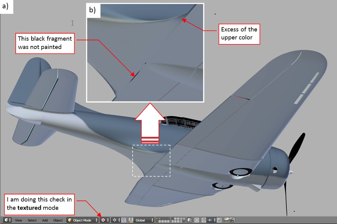
I exported the contents of the Camouflage layer to a file named camo.png, and tested it on the Blender model, in the Textured mode (as in figure “a”, below):
In this view you should look at the all edges that are mapped as the “borders” of the UV “islands”. In the enlarged view (as in figure “b”, above) you can easily see the missing pixels, which are displayed as black spots. I also carefully examined the border of the camouflage colors: there is always a local excess somewhere, which you have to remove in GIMP. I did this check having Blender window on one display, and the GIMP window on another. When I saw an error in Blender, I immediately fixed it in GIMP. When the source picture “accumulated” a few of such fixes, I refreshed its image in Blender. (As long as there are no painting layers in Blender, I still prefer to correct such errors in the GIMP source file).
When the image was verified, I incorporated it into the material scheme:
As you can see, I used an Attribute node to select the proper UV mapping (UVMap). The texture image is connected to the Diffuse slot in the generic shader node group (X.Textured Skin). For the time being I mixed it with the black anti-slip strip, “filtered” (by the Clamp node) from another picture (ref-aux.png, see this post, Figure 73-9). I will use it in this way until I paint this strip on the color image. Note that Blender allows you to mix images that use different UV maps (ref-aux.png texture uses UVTech mapping). It opens interesting possibilities for precise mapping of detailed emblems (as the squadron/personal insignia).
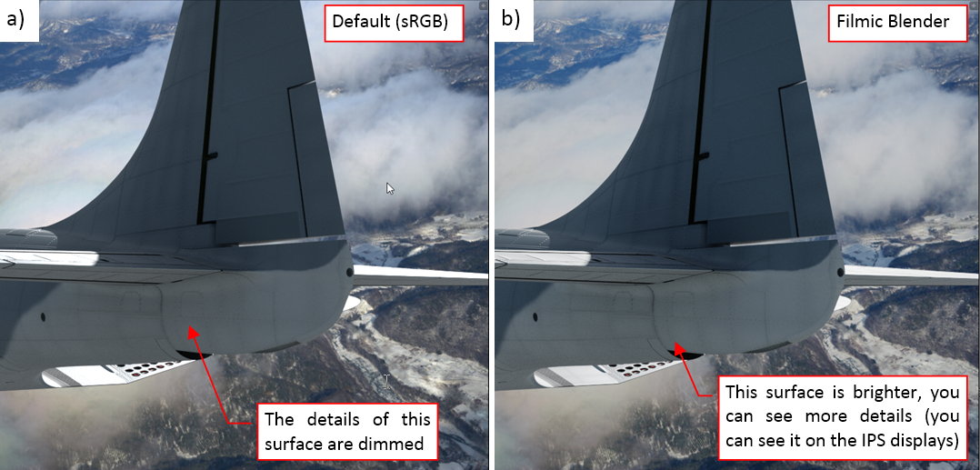
I already checked how the upper blue-gray surface looks like in previous post (see its final renders). Thus now I focused on the lighter, lower surfaces. Most of the things look good In the full sun, so I rendered the shadowed area of the tail (figure “a”, below):
Both paints used in this camouflage were non-specular (i.e. they have low reflectivity and high roughness). For such a surface in a shadow, the most visible texture is the color map. In our case (of the X.Textured Skin group), it means the color texture and the “dirt” component from the reflectivity texture. (X.Textured Skin group internally maps pixels from its Dirt slot onto the color texture, using the Multiply operator).
The technical details of the tail (rivets, seam lines, inspection doors) in figure “a”, above, are dimmed and hardly visible. It seems that rendering engine has troubles with such scenes, where the harsh light is accompanied by deep shadows. Thinking how to improve this effect, I thought about one of Blender Guru tutorials, about so-called dynamic range (the difference between the darkest and the brightest point in the picture). Blender Guru explained that the problem lies not in the renderer (Cycles), but in the another area: the color management. Following its recommendation, I installed alternative color management tables in my Blender. These tables were prepared by Troy Sobotka. You can download them from the Filmic Blender project site. The setup is simple *– I just had to replace the contents of Blender datafiles\colormanagement directory with the new files, provided by Troy. Although this package was mainly intended for indoor scenes, they still can somewhat improve such an outdoor scene like mine. You can see the result in figure “b”, above. The surfaces in the shadows now seems a little bit brighter and more natural. (IMPORTANT: to see it, you need a device which displays true 24-bit colors. For example - it can be an LCD display that uses the IPS technology. The less expensive LCD monitors, like those used in typical laptops, display only 18-bit colors).
Continued in the next post (the original article exceeded 10K characters /post limit of this forum)
Continuation of the previous post
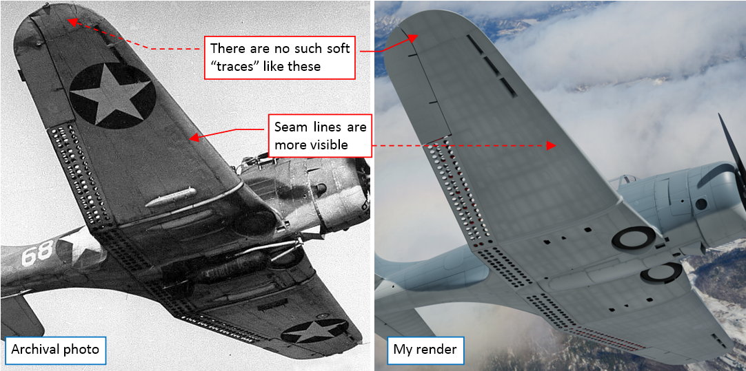
When I started preparing references (archival photos) for the next color texture (the “dirt image”), I realized that the actual dirt pattern from my reflectivity map does not match the reality:
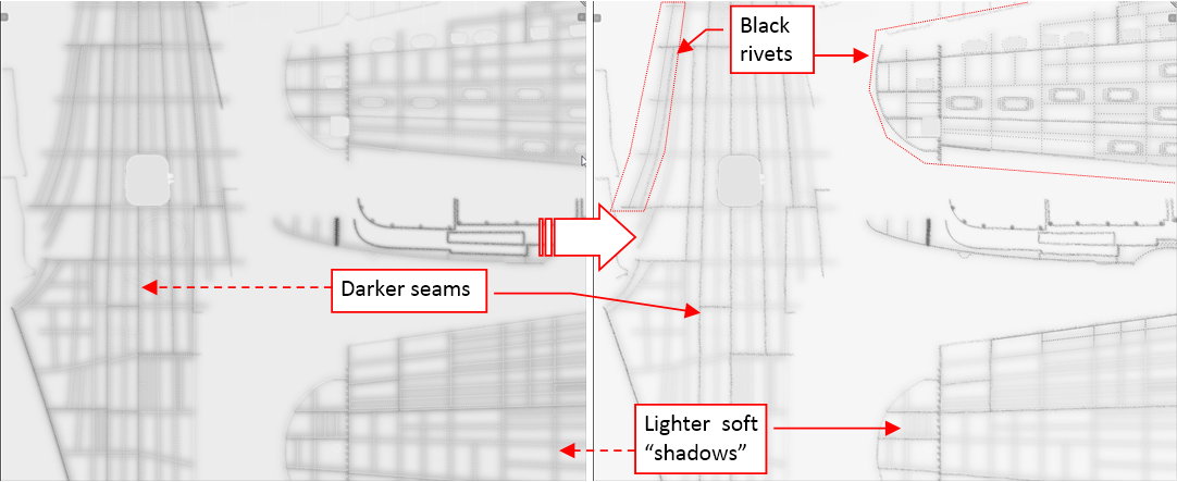
Of course, the archival photo on the left reveals a lot of soot streaks and other dirt, which I still have to paint. Nevertheless, the overall pattern visible on the real outer wings significantly differs from the pattern on my model (you can see it in the right picture). There were no soft “traces” along the rivet seams, as I painted on my model. The panel lines were more emphasized (some of them by the thick streaks, but this detail I will paint in the next post).
Actually, the whole dirt on my model comes from the reflectivity texture (ref-details.png image). As you can see in the scheme from my previous post, I connected the inverted content of my ref map to the Dirt slot. (Internally, pixels from this slot are multiplied with the pixels from the Diffuse slot – i.e. from the color map). Following these findings, I modified the source of the ref-details.png image – the Ref-Details layer in Inkscape:
You can find this picture in the Inkscape source file that accompanies this post. I modified it by reducing the opacity of soft traces along rivet seams (the Blur sublayer), while increasing visibility of the panel lines (the Grunge sublayer). The white highlights of the rivets, which look good on the darker upper surfaces, disappear now on the lighter bottom of the wing. Thus I modified this element, adding there an additional clone of the rivets seams. I set its color to into black (using SVG filters), and clipped (using SVG mask feature) to the areas of the bottom wing and lowest parts of the fuselage.
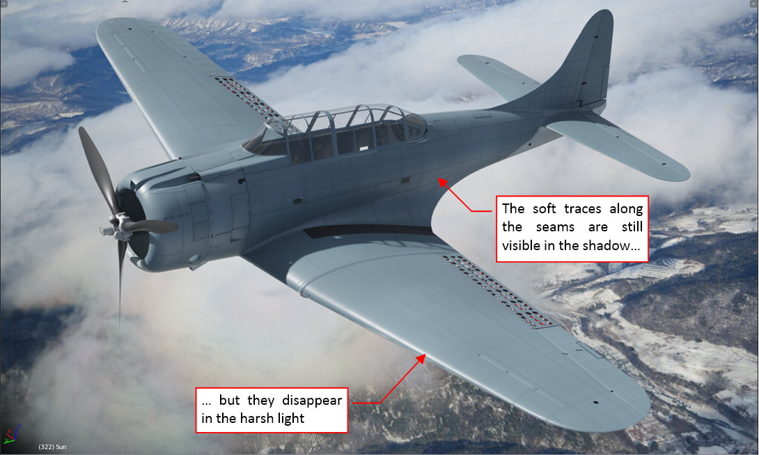
You can see the effects of this new ref/dirt texture in the figure below:
All the technical details are more visible now. The delicate soft treads along the rivet seams still appear in the shadowed areas, but vanish in the harsh light:
In overall, this model seems to be cleaner than it was at the end of the previous post. (It looks like a factory-fresh aircraft). I will work on this issue (by adding more dirt and weathering), and report my progress in two weeks.
In this source *.blend file you can evaluate yourself the current version of the model, and here are theInkscape and GIMP source files of its textures. [SUB][SUP]Because of the large size of the original GIMP file (.xcf), this post is accompanied by its smaller version (2048x2048px), packed into .zip file. I think that such a version is sufficient for checking all the details of this image (the structure of its layers, their opacities and mixing functions). The resulting textures (4096x4096) are packed into accompanying Blender file.[/SUP][/SUB]
Just thinking about the patterns of dirt: near the tip of the wing the flow (and therefore the deposition of any dirt) will be greatly affected by the tip vortex, so the grunge won’t necessarily be laid down the way you might expect.
The other thing is the heavy line of dirt just back from the leading edge on the underside. My guess is that the leading edge panel overlaps the underside panel, given a natural tripping point to the boundary layer there. The old section this plane uses was probably at turbulent flow there anyway, or close to it. The old NACA sections and similar rarely sustain laminar flow much past 10% of the chord even under optimal conditions. Any seam there could be expected to accumulate quite a bit of dirt.
Thank you for following!
I will simply follow the photos. (I already learned that creating dirt pattern “by instinct” leads to results that significantly differ from the reality :)).
You are definitely right: this is a classic (i.e. “turbulent”) airfoil (NACA-2415), and the leading edge panel overlaps the next one. I will recreate this heavy line of dirt along the leading edge - it repeats on some photos.
In this post I will work on the weathering effects of the color texture, while in the next one I will add scratches and some other remaining details.
The weathering effects that you can observe on the aircraft from WWII era are quite “dramatic”. The paints used in mid-20[SUP]th[/SUP] century were not as chemically “stable” as the contemporary coats, thus they could change their hues in few months of intense service. The archival color photos below show an extreme case of this effect:
These photos were taken by Frank Sherschel on 14[SUP]th[/SUP] November 1942, for the “Life” magazine. The SBD-3s depicted on the pictures belonged to VMSB-241 squadron, stationed at Midway in that time. Marines received these aircraft in July 1942, but all of them were already used before - most probably on the U.S. Navy carriers. I think that in November 1942 these SBDs had accumulated about 10-11 months of the war service. I will use them as an extreme case of the weathering. (It is always good idea to recreate such an ultimate case in the texture, because you can always make your model “newer” by decreasing intensities of the weathering layers. On the other hand, you cannot use more than the 100% of their intensities, thus you cannot make your model “older” than you initially painted).
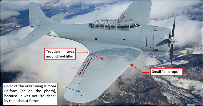
Having historical color photos of several airplanes used by the same squadron, you can easily determine the general pattern of the stains, smudges and scratches. This pattern repeats with some random variations on every aircraft. It seems that such a radial engine like R-1820 emitted a lot of oil – in their exhaust fumes and in the air flowing from the NACA cowling. (Because of the high “oil consumption” of the R-1820 the oil tank in the SBD was quite large). The non-specular paint of the two-color Navy camouflage absorbed this oil mixed with the soot from exhaust fumes, creating characteristic dark traces along the fuselage and the center wing. The crew most often walked on the center wing, thus you can see on its upper surface the lighter traces along dome rivets seams and darker, “trodden” spaces in between. There are also some scratches in the paint. Some of them exposed the yellow primer, while the others reached the bare metal of the aircraft skin. (Thus I assume that the first layer of the Douglas primer had a yellow/orange color).
You can also notice some white splashes on the outer wings (traces of the coral sand from the atoll?), as well as the repainted areas around the tactical numbers. (On a black-and-white photo, it would be extremely difficult to distinguish these repainted areas from the oil/fumes traces).
What is interesting – in spite of the non-specular camouflage of these aircraft, you still can see a specular highlight at the wing root (as in figure “b”, above).
The key elements of the weathering effect still depend on the technical details of the aircraft skin: rivets and panel seams, bolt heads, inspection doors. However, their pattern is so random, that I cannot recreate them in the SVG image, as I did in the case of the reflectivity map. Thus we need a reference picture of the skin details for painting the color (diffuse) texture. It has to be mapped in the same UV layout (UVMap) as the color texture. To do this, I composed from the key layers of the SVG drawing an auxiliary image, mapped in the UVTech layout. Then I quickly transformed it into UVMap layout using the Bake feature:
The old Blender Renderer engine is a better tool for such a direct transformation of a single texture than the Cycles Renderer. In the Blender file that accompanies this article, I created a dedicated screen layout for this purpose. It is named Texture Baking. You can find there a simple script that I used to switch the UV layout of all model meshes between UVTech and UVMap. To bake a texture from UVTech to UVMap layout, you have to switch the current rendering engine to Blender Renderer and disable nodes in the B.Skin.Camouflage material. Then assign the image (mapped in the UVTech coordinates) to its single Blender Render texture assigned to B.Skin.Camouflage material, named Image for Baking. When you click the Render:Bake button, it will generate the resulting texture (in the UVMap coordinates) in the Test image, which you can see in the UV/Image Editor. You can use Image:Save As command to save it to an external raster file.
I created such a reference image for each SBD version I have modeled (SBD-1, SBD-3, and SBD-5), and placed all of them in GIMP:
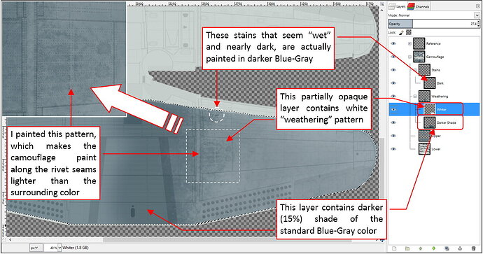
The darker areas in this weathering appear between the rivets seams. I decided that it will be easier to recreate them using one layer of darker camouflage color, overlaid by partially opaque layer that contains the weathering pattern (in white). First I painted in this way the right outer wing:
I used this “sample” for testing if such a pattern looks good in the final image:
I think that it looks acceptable. Thus I started to paint in this way the weathering of the whole upper surface.
I create the basic pattern of the lighter traces along rivet seams in four steps:
First I painted the “overall noise” with an “acrylic brush” tool (figure “a”, above). Then I changed the tool shape to “pencil” and draw thin lines along rivet seams (figure “b”, above). In the next step I used Eraser to make this pattern more random (figure “c”, above). Finally, I filled it again with light touches of an irregular brush, to lighten the overall effect (figure “d”, above). (This last step is optional, depends how this fragment looks like on the reference picture).
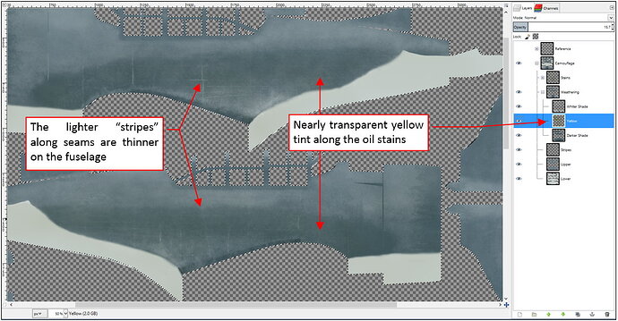
Figure below shows the resulting weathering pattern on the fuselage:
As you can see, it differs from the pattern on the center wing. The lighter traces along rivet seams are thinner, the color is more uniform. Using a separate layer, I added a yellow tint to the darker areas.
Continued in the next post (this article exceeded the 10 000 chars/per post limit)
Continuation of the previous post
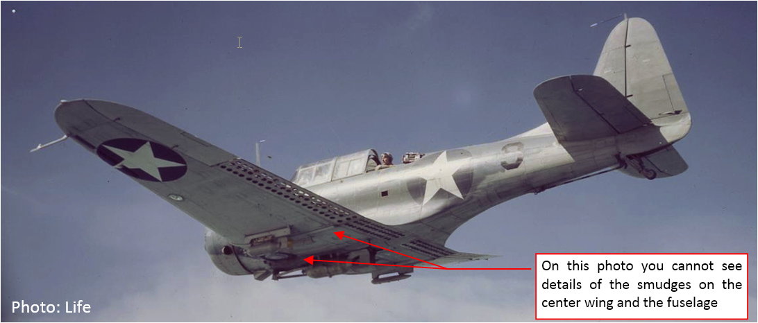
Unfortunately, in Frank Sherschel’s collection there is only one, small photo which shows the bottom surfaces of an SBD from this squadron:
You can identify there some smudges on the outer wing and rear fuselage. However, you cannot determine the dirt pattern for the center wing and the engine cowling. (You can only say that they are dirty).
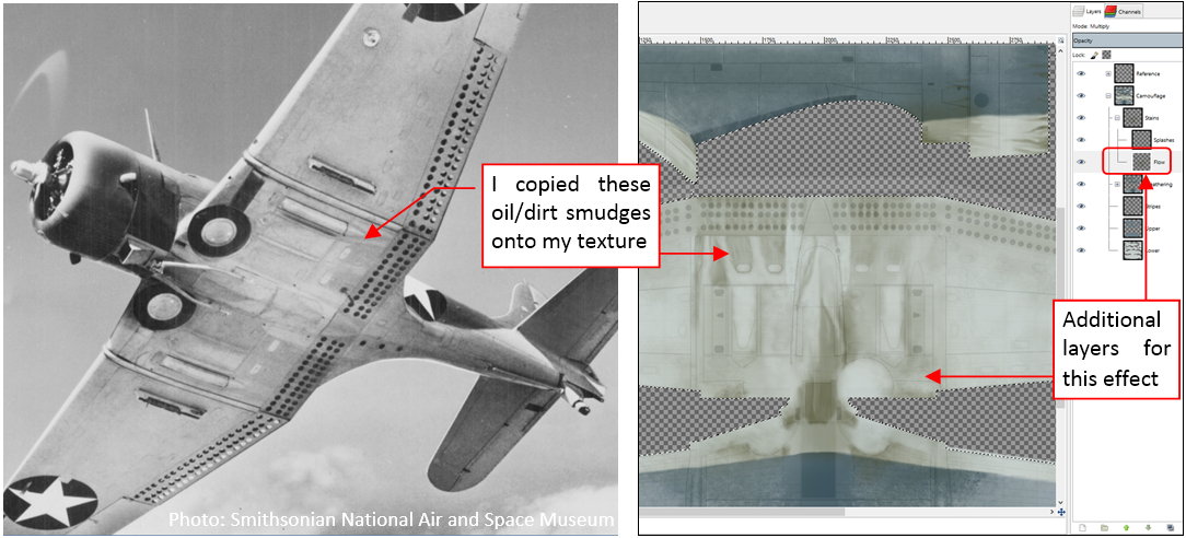
Well, in this case I had to use another, black and white photo as the reference. This photo shows clearly the center wing section of a typical aircraft:
As you can see, I recreated in my image the exact copy of the smudges from this SBD-4 center wing. They are placed on another layer (Flow) in the Stains layer group.
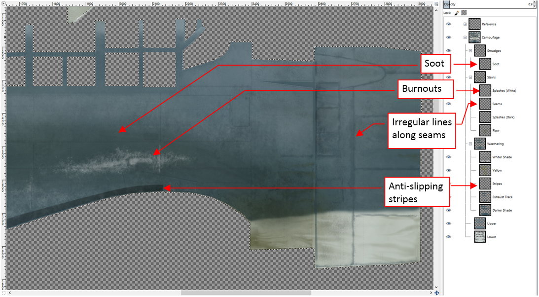
Finally, I enriched this basic dirt pattern with all the additional details visible on the reference photos: white “burnouts” on the fuselage sides, discrete traces of soot. There are also irregular, darker lines along some of the panel seams:
Each of these elements has its own color and layer. Note that the darker lines along panel seams extend across the upper and lower surfaces. I painted them using the same color, but on the bottom surfaces they are more transparent, to obtain the appropriate contrast. (Painting them, I used a 50% opaque mask for the bottom surfaces).
Figure below shows this “weathered” diffuse texture on the model:
Frankly speaking, I am still not satisfied with these results. This weathering requires some minor adjustments. For example: on the reference photos it has a slightly different hue. The fuselage below the tailplane also requires some fixes.
While painting all these weathering effects, I came to conclusion that I cannot re-use them without any modification in the three-color camouflage, used in the SBD-5s and -6s. Thus I will not split the color texture into three interchangeable parts, as I announced in my previous post. I will have to prepare few alternate color textures instead:
- A colorful pre-war painting scheme (orange wings!), without weathering for the brand-new SBD-1s from the Marines squadrons (+ eventually the later single Light Gray color scheme, as visible in color photos preserved in the Smithsonian Air And Space Museum);
- Two-color Navy scheme for the SBD-2,-3 and -4s (described in this post);
- Three-color semi-gloss Navy scheme for SBD-5s and -6s (+ eventually the white variation of this for the SBD-5 and -6 scheme, using on the Atlantic areas);
Of course, I will reuse fragments of the weathering pattern described here in the three-color scheme for the SBD-5s and -6s. However, before I do it, I have to finish this color texture. Thus in the next post I will fix the minor flaws described above, and recreate the scratches visible on the reference photos. Then I will apply the “decals” – national insignia, tactical numbers, etc.
In this source *.blend file you can evaluate yourself the current version of the model, here is the GIMP source file of its textures. [SUB]Because of the large size of the original GIMP file (.xcf), this post is accompanied by its smaller version (2048x2048px), packed into .zip file. I think that such a version is sufficient for checking all the details of this image (the structure of its layers, their opacities and mixing functions). The resulting textures (4096x4096) are packed into accompanying Blender file.[/SUB]
Witold, it’s looking amazing. I’m in awe of your talents.
My guess is that it would have been a zinc chromate primer, which is still in common use as a primer for aluminium. That would explain the colour.
You can also notice some white splashes on the outer wings (traces of the coral sand from the atoll?)
Probably not. I can’t see sand staying attached. My guess is they are either chips in the paint or splashes of some fluid.
What is interesting – in spite of the non-specular camouflage of these aircraft, you still can see a specular highlight at the wing root (as in figure “b”, above).
Given the location (just adjacent to the non-slip walking strip) this specular highlight could well be the result of boots repeatedly skidding from the wing root fillet to the non-slip strip, thereby wearing the paint back to bare metal. Such a motion would probably be natural when getting into or out of the cockpit in a hurry.
Thanks for the details on the skinning process. I can see them being a useful reference for all sorts of projects.
thorst, Gumboots, thank you for following!
I studied this area again (see my “weekly progress” post below), and recreated it on the render. This is not shining metal, but glossy, black continuation of the anti-slip strip. It is visible on some SBDs, especially SBD-2s ane SBD-3s.
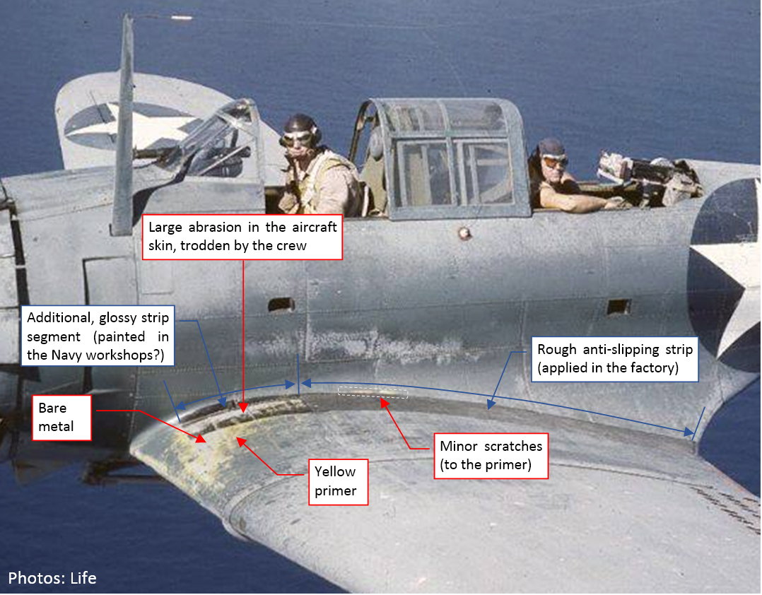
It seems that Douglas used a high-quality paint for their SBDs, because I cannot find any trace of chips/flakes, even on such a worn-out aircraft as this from VSMB-241 (see figure below). However, you can see some scratches on the center wing, trodden by the crew:
In the photo above, the minor scratches are yellow, because Douglas used a yellow layer of Zinc Chromate primer below the camouflage paint. (The interiors were painted with another layer of the Zinc Chromate, mixed with Lamp Black to obtain a darker, greenish hue).
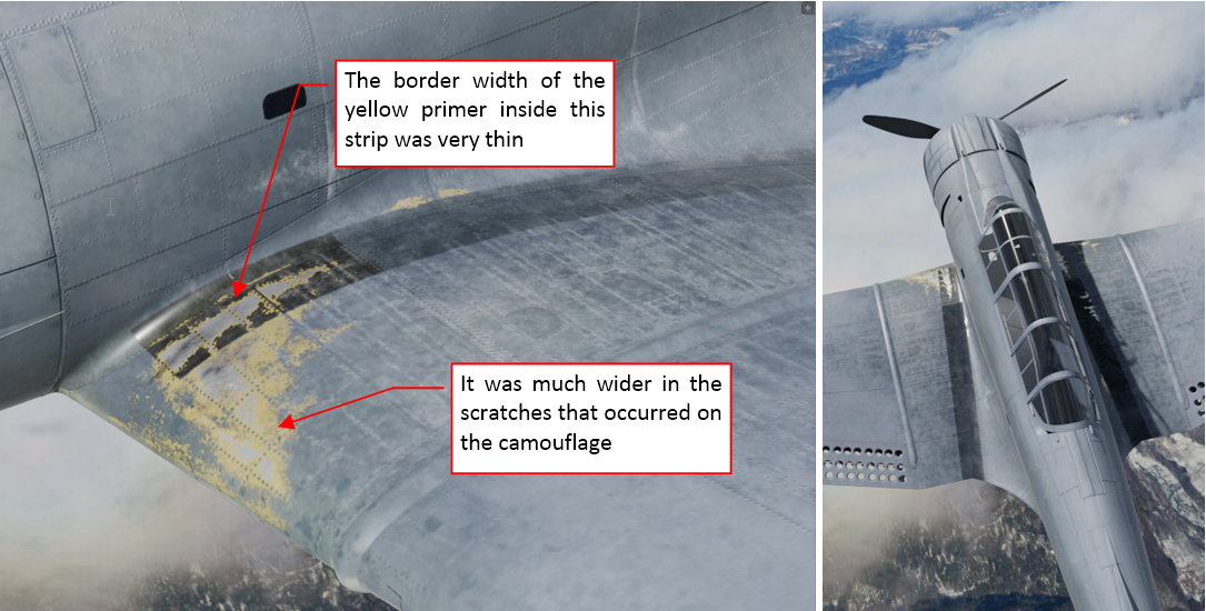
However, the larger area along the leading edge was often trodden to the bare metal, which you can see in the photo. This scratch has a typical, irregular band of the primer around its borders. In this post I will recreate these abrasions.
The aircraft producer anticipated this kind of damage (at least to some extent), placing a thick, rough, anti-slip strip along the fuselage. It seems to be made of a black, rough material, glued (?) to the aircraft skin (as in the picture above), and spans from the trailing edge to the main spar. However, the most “visited” by the servicemen area in the front of this spar had no such a cover. On some SBDs (including the one on the photo above) you can find a glossy, black continuation of the anti-slip strip. I suppose that it was added in the Navy workshops. It seems to be simply painted using a typical black paint, thus was more prone to the abrasion (as you can see in the photo).
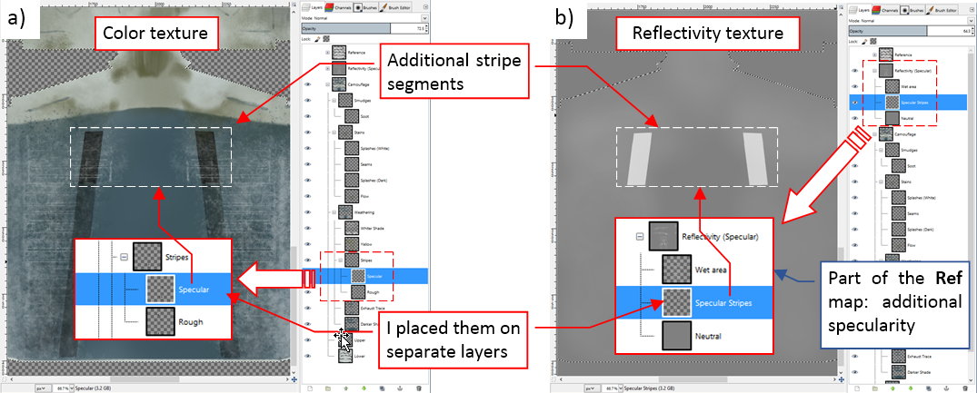
To recreate the effects from this archival photo, I had to paint this glossy black area first. It requires changes in the two textures: color map (because it was black) and reflectivity map (because it was glossy). I created in the source GIMP file separate layers to reproduce these shapes. This way I can simply turn them off while painting another aircraft that did not have this feature (like most of the SBD-5s and -6s). Figure “a”, below, shows the color texture image, while figure “b” shows the additional reflectivity map (they share the same GIMP file):
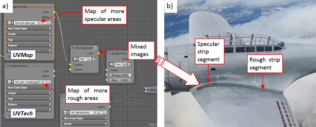
Note that I introduced here another part of the reflectivity texture: the map of the areas that are more specular than other. This is a natural addition to the ref-aux.png map that I used in this post to make the remaining anti-slip strip more rough. There are also some other areas that look more “wet” (specular) than the others. For example – the fuselage sides (because of the small amounts of the oil, spreaded from the engine). I painted them in GIMP in a lighter gray, on a separate layer named Wet area (see Figure “b”, above). I saved this image to a file named ref-aux-spec.jpg. However, I could not simple merge it with the ref-aux.png map, because it uses the different UV layout (UVTech). Thus I had to join these images in Blender, using special node that mixes two grayscale pictures (as in Figure “a”, below):
For the brevity I renamed the ref-aux.png file to ref-aux-rough.png. Figure “b”, above, shows these updated textures on the rendered picture. Frankly speaking, the weak increase in the specularity of the fuselage sides is not visible here, but you can see the much more accented difference between the reflectivity of the forward and the rear anti-slip strip segments.
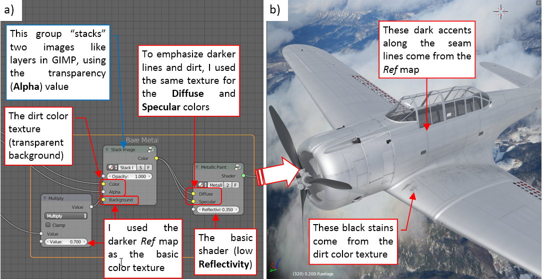
I am going to recreate the scratches that you can see in the archival photo using so-called shader mask. Thus, in addition to the weathered camouflage shader that I used so far, I need a “bare metal” shader, which looks like a rough duralumin skin. Figure below shows such a thing:
Note that this shader uses the ref_details.png image (see Figure 73-4 in this post) as the base color texture (for the Diffuse as well as the Specular colors). The dark lines from this image create appropriate shadows along the seam lines. I just made this input image somewhat darker (using a Multiple node), to transform the semi-white background color of the original ref_details.png image into metallic gray. What’s surprising, it’s better to use a fixed Reflectivity for such rough (low-reflectivity) metallic shaders. When I tried to use the same ref_details.png image as the reflectivity map for this case, it made the panel seams lighter, reverting the effects of the color texture.
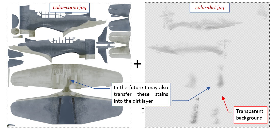
To share the dirt between the “bare metal” and the camouflage shaders, I separated it from the color texture. I named the two resulting images as color-camo.jpg (the weathered camouflage) and color-dirt.png (the soot traces and some stains on transparent background). I used the Stack Image nodes (see Figure “a”, above) to combine them with corresponding backgrounds, like the layers in GIMP. Figure below shows these two components of the color texture image:
In the color-dirt.png image I initially grouped only the soot traces. It is possible that I will also transfer other layers there. (We will see if I have to do this during the work on the pre-war “natural finish” painting scheme of the SBD-1).
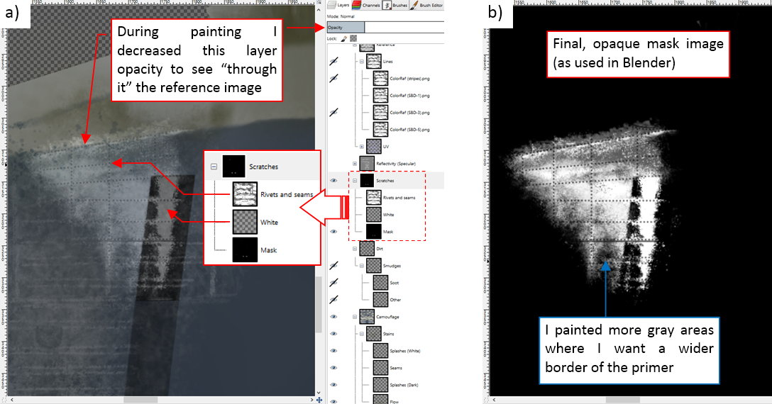
Then I prepared a B/W “shader mask”, painting white, feathered scratches on a black background:
As you can see in Figure “a”, above, I decreased the opacity of these shader mask layers while painting, using as the reference the camouflage from the layers below. I also used a copy of the reference image (layer Rivets and seams) to precisely recreate technical details visible inside this scratch. (SBD had flush rivets on this area. Usually the paint remains on their heads even when there is bare metal around). Figure “b”, above, shows the final material mask. I saved it to a file named mask-scratches.jpg.
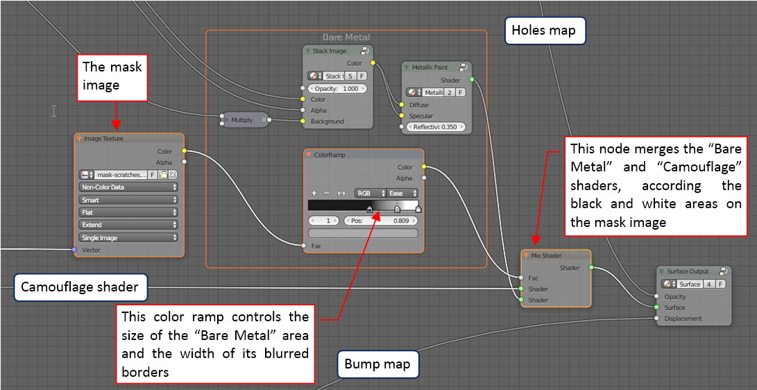
Below you can see how I used this mask in the material scheme:
Note that I placed a Color Ramp strip between the mask and the Mix Shader node. The pattern, set in this node, controls the ultimate size of the scratches, and the width of the transition area. (The transition area is “feathered” border of these bare metal scratches, where the share of both shaders is greater than 0). For example, if I want to get the “chips” effect (bare metal areas with sharp borders) I should switch this color ramp mode from Ease to Constant. (It creates a strip that contains just sharp black and white spans, without any “gray transition” between them).
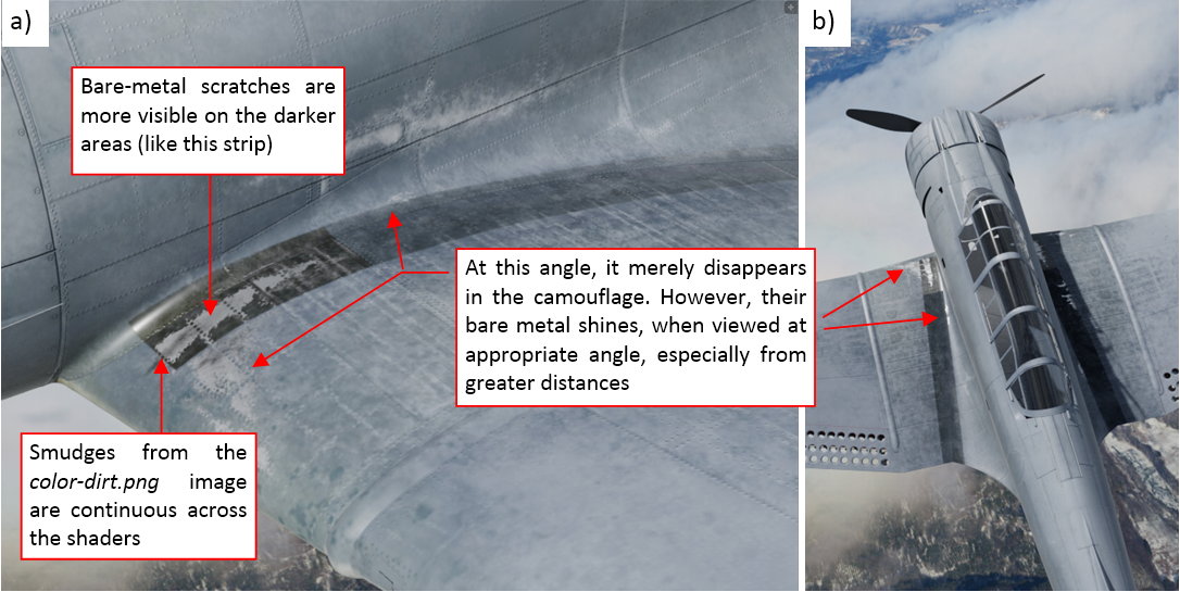
The result of this shader mask looks like the test render below:
The bare metal scratches look good on the dark background (like the anti-slip strip). For certain viewing angles they disappear in the camouflage, because of their gray color (as in Figure “a”, above). Still, they can shine (as in Figure “B”, above) when you view them from other sides, especially when you do it from greater distances. (This shining effect looks quite convincing – this is the advantage of this method over scratches painted directly on the color texture).
Continued in the post below [SUB][SUP](the original article exceeded the 10k characters limit)[/SUP][/SUB]
Continuation of the previous post
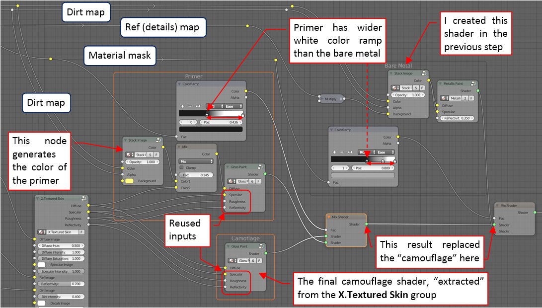
Now, let’s add the primer to these abrasions! This means that we have to add yet another shader to our material scheme. It is similar to the camouflage shader, with one exception: it has to have a uniform yellow color, instead of the camouflage texture. To reuse all the other settings, I decided to “extract” the final Gloss Paint shader from the X.Textured Skin group. Figure below shows the modified material scheme:
I “cascaded” the camouflage, primer and bare metal shaders, using two Mix Shader nodes. In general, each Mix Shader could use a different mask image. In this case both use the same input mask, but each one modifies it in a different way, using its Color Ramp node.
You can see the result below:
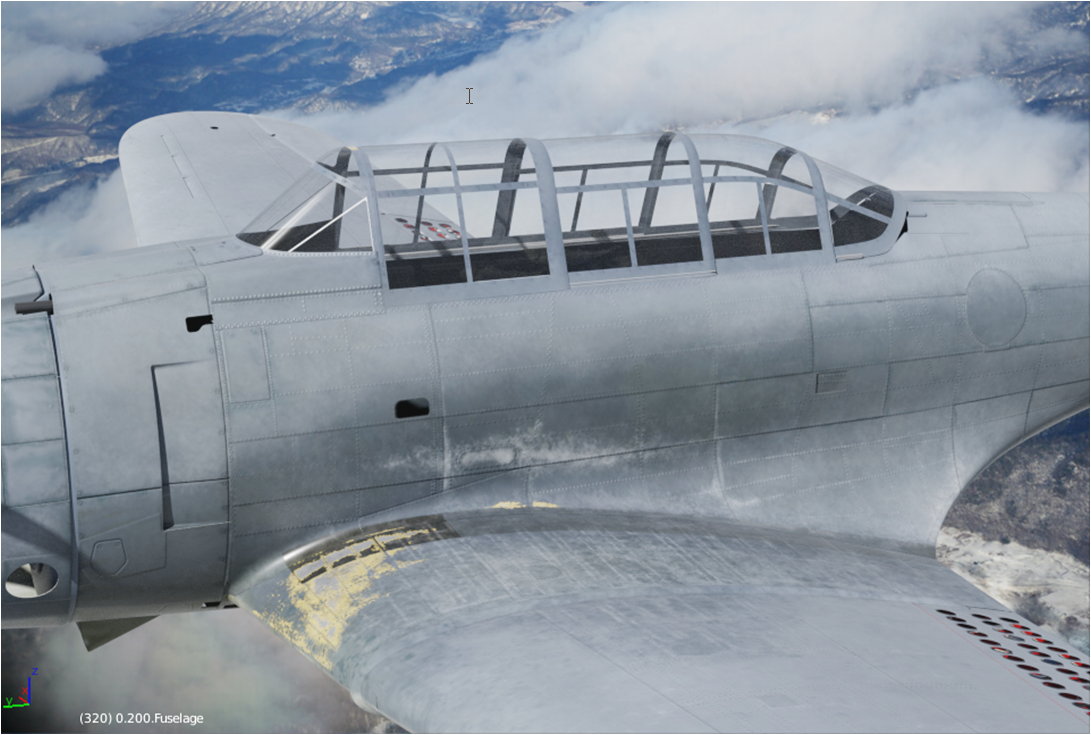
I think that it looks good enough. These and other details bring the final effect closer to the original photo from the beginning of this post (compare the picture below with the first picture in the previous post):
Of course, there are still differences. (For example - I have impression, that I should use stronger sunlight in my scene, to obtain such a high contrast between the lighter and darker areas as in the original photo). Well, I will work on these issues later.
Using the shader setup presenting in this post, painting all other scratches is a breeze: you just have to add another white splash on the shader mask image.
In the next post I will prepare the “decals” texture, containing national insignia, tactical numbers, and some service labels. (I will add more of these labels during the detailing phase, when I review each area of the aircraft skin).
In this source *.blend file you can evaluate yourself the current version of the model, and here is the GIMP source file of its textures. [SUP]Because of the large size of the original GIMP file (.xcf), this post is accompanied by its smaller version (2048x2048px), packed into .zip file. I think that such a version is sufficient for checking all the details of this image (the structure of its layers, their opacities and mixing functions). The resulting textures (4096x4096) are packed into accompanying Blender file.[/SUP]
You think so? ![]()
shakes head and laughs Most people would have thought it looked good enough six months ago. But do keep going. This is amazing to watch.
