Hi all,
I have had the opportunity to do some Schlieren imaging a couple of days ago.
For those of you who are not familiar with this, its a way of visualizing density changes in gasses.
The most common phenomenon that can be observed outside is the “heat rays” coming of hot asphalt on a hot summer day.
There are a number of applications for Schlieren imaging. In my experience the process was applied to a supersonic wind tunnel test.
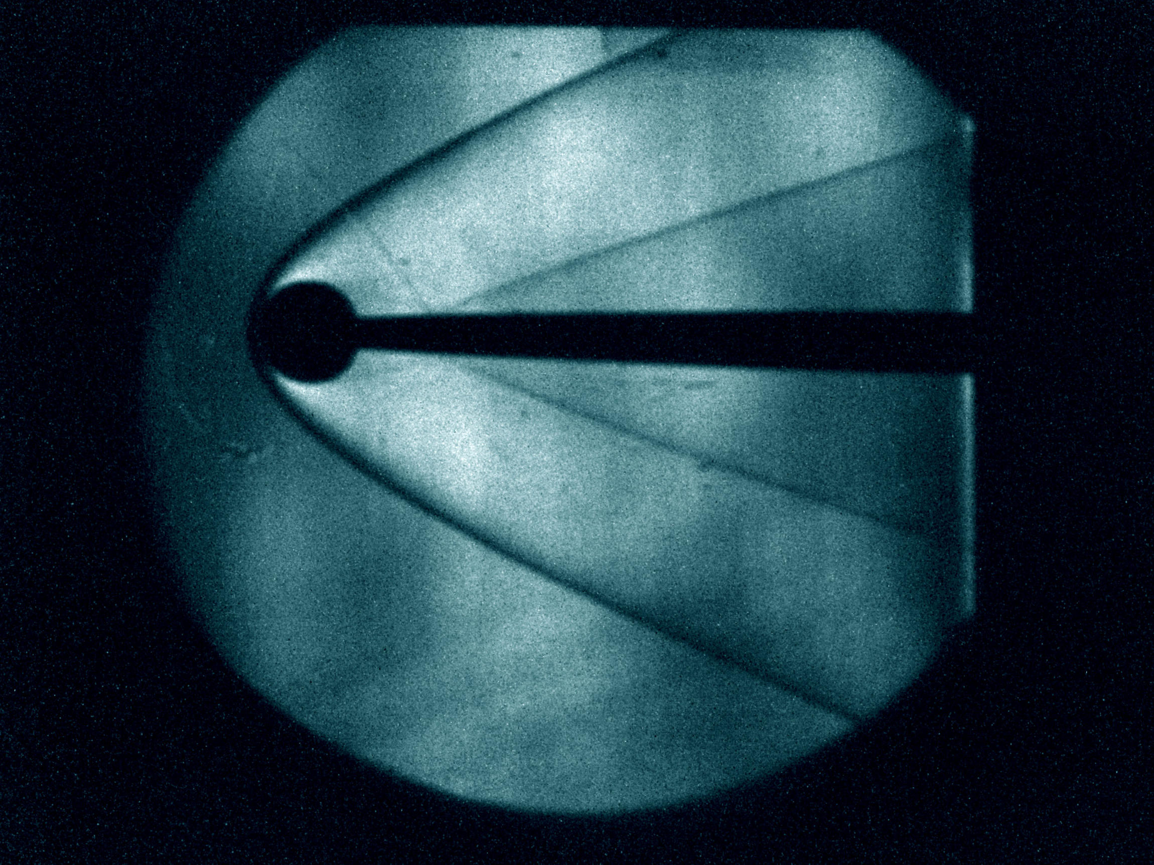
At high speeds above Mach 1 shock waves form before objects, and using Schlieren imaging we where able to photograph them.
Four different objects where placed in the test section of the wind tunnel, and as it was turned on the following images where captured…
The original images are quite dim and slightly distorted, thus they where corrected using Photoshop. (because we had to turn of the lights, except the source light, the images came out grainy, so sorry about that)
And of course I had to take the liberty of adding some color grading to the photos
Hope y’all enjoy!
Super cool. I looked up schlieren imaging on wikipedia a while ago after watching it on a science show, but I couldn’t get how it works.
If you do know, can you give an exact explanation of how this works?
@ (jay)
No there is no sonic boom, as it is caused by a shock wave moving past you causing the quick pressure change that your ear registers as sound. In the case of the wind tunnel the shockwave was stationary so no boom is heard. (same with people on board supersonic planes, they hear no boom because they are moving at the same speed as the plane is)
That said, the thing is beastly loud so ear protection was definitely necessary.
As far as the image goes dark areas represent high density and light areas low density.
I have attached an image that explains the shock-waves (figure is taken from Andreson Aerodynamics book)
This is similar to what we had for our setup so ill go from here.
Schlieren imaging uses the fact that with a density change the light gets refracted. The refracted light rays then do not follow the same path as the other rays, thus upon getting to the point where the knife edge is located, not all the light now has that point as its focal point. Depending on how the light was refracted, the rays would either be further away from the knife thus brighter or closer to it and dimmer. This produces an image on the wall that correlates the light refraction in terms of brightness.
Oh this is one of the laboratory classes i have to take, i thought the images where pretty cool so I thought I would share them.
And yeah I wanna do it again … I think I might actually for another experiment further into the semester, but i don’t know for sure.
BTW I found a person on YouTube that posted actual videos of the experiment in 2008, check them out!


 … I think I might actually for another experiment further into the semester, but i don’t know for sure.