Sci Fi Project Trailer pre-production Finally begins!

This will be a journey in terms of growing my skills and posting regularly. I’ve been working on a military helicopter documentary for the past 7 years and while it continues to make progress, my brain needs a new challenge. To that end, this will be the first post of a long series of updates on an animated trailer idea I have had on the back burner for far too long. Life is short, I’m not getting any younger, so I might as well start today. This first post may be a bit underwhelming but it is the beginning of something I hope will be fun an exciting once it is complete.
The attached image is a series of concept design sketches, based on a rough formed Blender model mesh (Blender 2.91 under Windows 7), exported as a view port render and then doodled some details on via Photoshop (5.51). In true concept art fashion, I kept this series of thumbnails small and low-res to avoid over detailing anything. I wanted to play with forms and shapes around the air intakes specifically and see how it would look from this front, 3/4 front right angle view low as the craft comes in for a landing.
Ideally I would have worked on this in Krita, but I didn’t have the time.

Next step will be to downsize my selection to three versions and detail them further before taking it into Krita and making a nice concept drawing. Until next post…

4 Likes

While I did down select to three versions that I liked, my schedule did not allow time for concept art.
I’m diving into one of the details that I prefer for the intakes with the few moments that I have available today.
Basically, this is one panel of a set that is supposed to align, in a ring like fashion, around the intake duct.
This image is a test from a very quickly put together armature rig (i.e. bone) to see if I can get it to work in principle.
The restraint bone is “pushing back” on the Y axis in an effort to make the other two bones hinge at where they connect. So far so good. But when I parent some panel meshes to the bones, the forefront panel does not pivot at the place between the two panels. I have assigned the origin (of the fore panel) to the same location as the “head” of the corresponding bone so it should hinge correctly. Not sure what’s gone wrong but I will take another stab at it during the week as time permits.

1 Like

Good to see this “taking off” :blush:
I’m not sure I understand the hinge issue from what you describe without a blend file but it looks like it is doing what I’d expect. Is this an IK “knee” type of issue perhaps?

Hey there Paul! You mean my post brought you back to the forum? I’m honored! :grinning:

The hinge issue utilizing bones wasn’t working as planned because the “rigged” knee would twist or turn at various moments- even with constraints. I’ve seen it work in a few tutorials on Youtube but it wasn’t working for me. In many instances, the control bone would either go “through” the whole leg with no effect , or it would engage the rest of the armature only after I pulled the control bone away on the Y axis and then forward again. There was always a delay before the movement began. And this wasn’t even an animated test- this was just moving with mouse and keyboard.
After that, I decided on another technique…

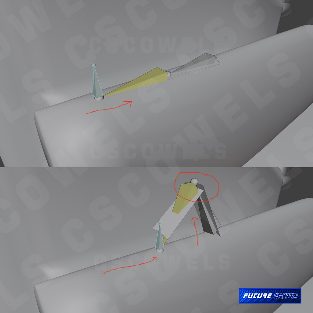
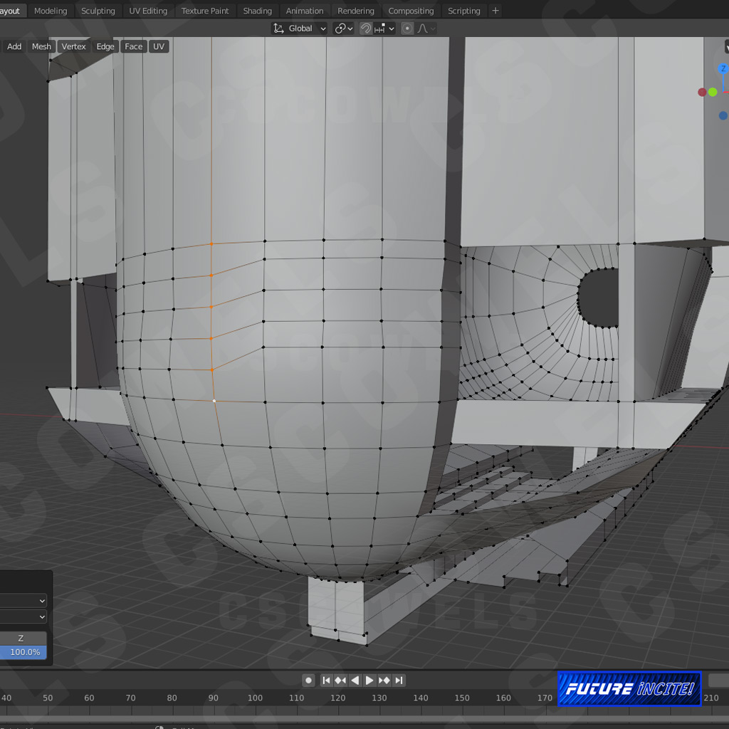
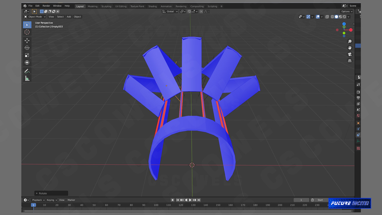
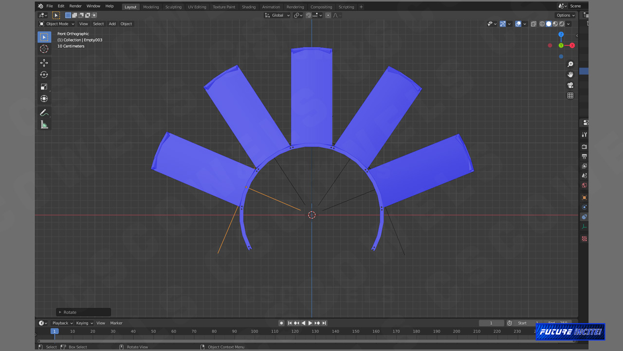
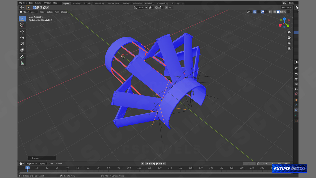
Constraints and dampers seemed better suited for what I wanted to do. This time, I created a half-cylinder, and using inset and extrude, created panels with an underlying framework.
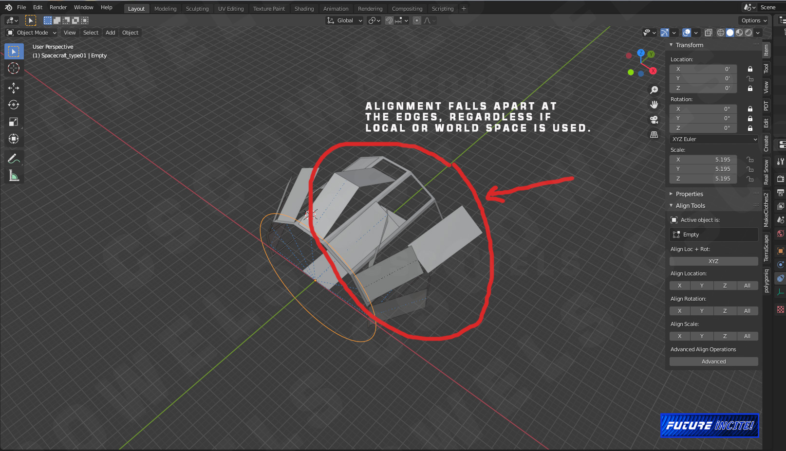
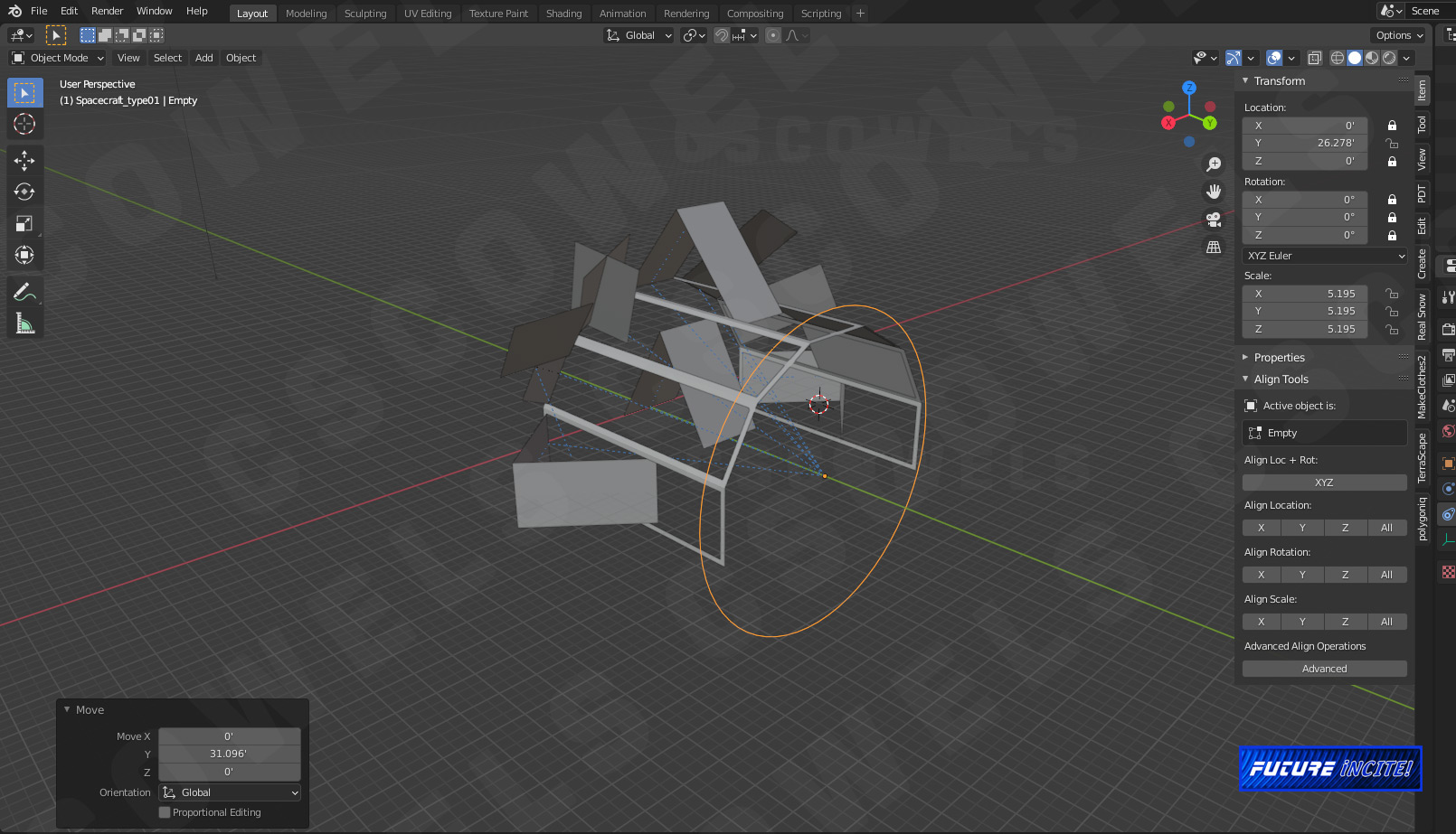
So far so good. I used all of my settings from the base form folding panel and basically copied and pasted the settings on to each individual panel set. At this point, I thought my theory was sound… until I tried to fold the flaps using the control ring. As before, the panel sets on the “shoulders” or “corners” of the frame work go way out of wack.

I tried local space and world space settings. I tried applying and not applying rotation and scale transforms. The problem persists. What am I missing here?

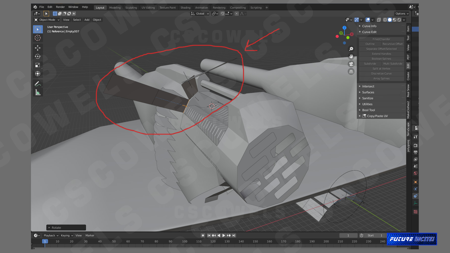
The above rear view shows how the panels segments on the top, which utilize the X axis and the panels on the side, utilizing the Z axis, fold as expected. The other segments… Uggh.

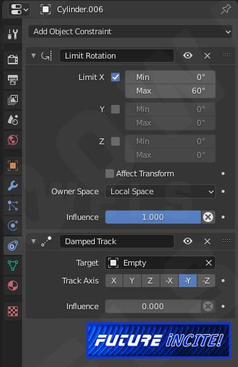
These constraint settings are for the parent panel, the panel that initiates the fold by rotating on the X-axis.

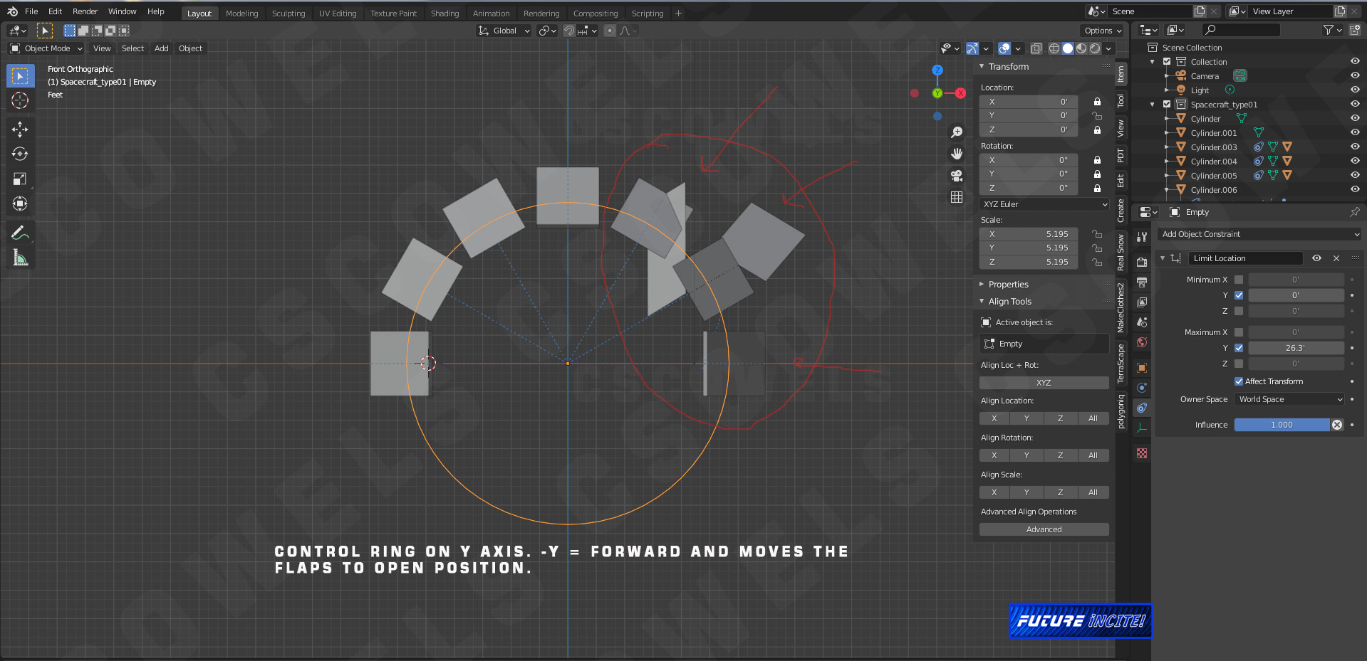
The Damped Track constraint is for the control ring, that moves along the Y axis. As I move the ring forward, the panels/petals open up. But more on that later…

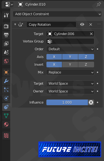
These above constraints are for the child panel that inversely follows the parent. In other words, when the parent panel folds on the X-axis, the child mirrors the action, with both panels meeting in the middle as it were to create a “tenting” action. I tried variations with Target as Local and World Space and Owner as Local and World Space. I tried different Axis combinations. Nada. So, on to my next brain storm…

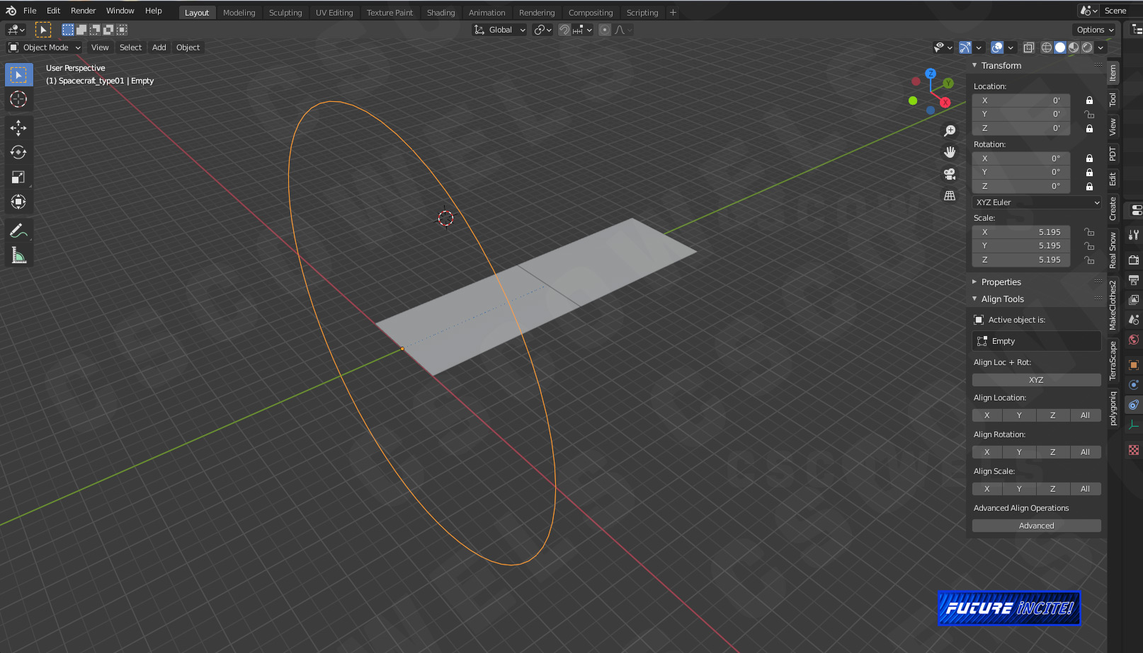
So I deleted the framework and started fresh with just the simple parent and child panels to verify that I hadn’t made any errant settings. One thing that irks me is that, the intensity setting is like “all or nothing”.
At any intensity setting, the slightest movement of the Control ring completes the entire movement. It’s like a jump-cut in a movie. There is no ease and out. I tried different intensities… no dice. I tried changing the location constraint on the Control ring and that became a lesson in diminishing returns; the farther I extended the constraint, distance wise, while it did make the movement of the panels slower, it also didn’t allow them to close fully.

In terms of movement cycles, I found that an intensity setting of .333 was able to provide me with the 60 degree angle fold I wanted. But it just snaps into place. So…

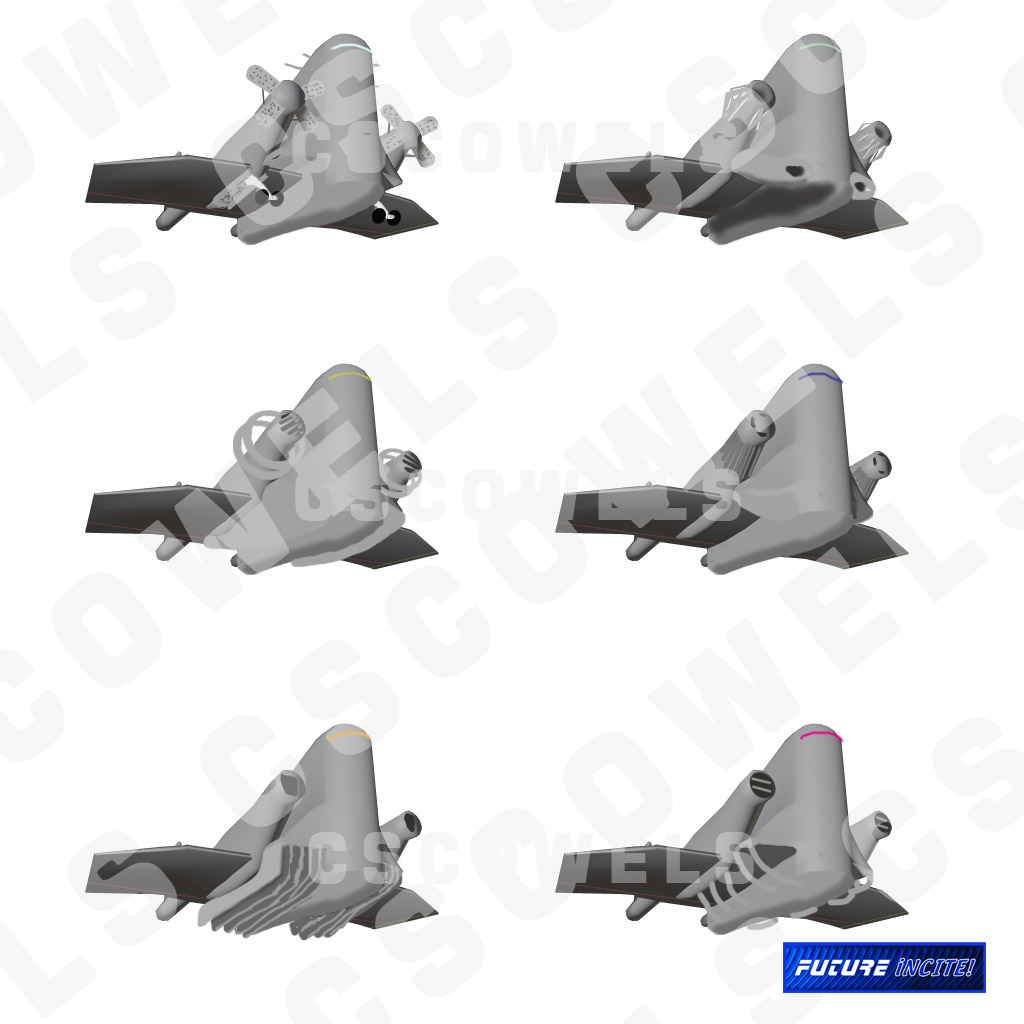
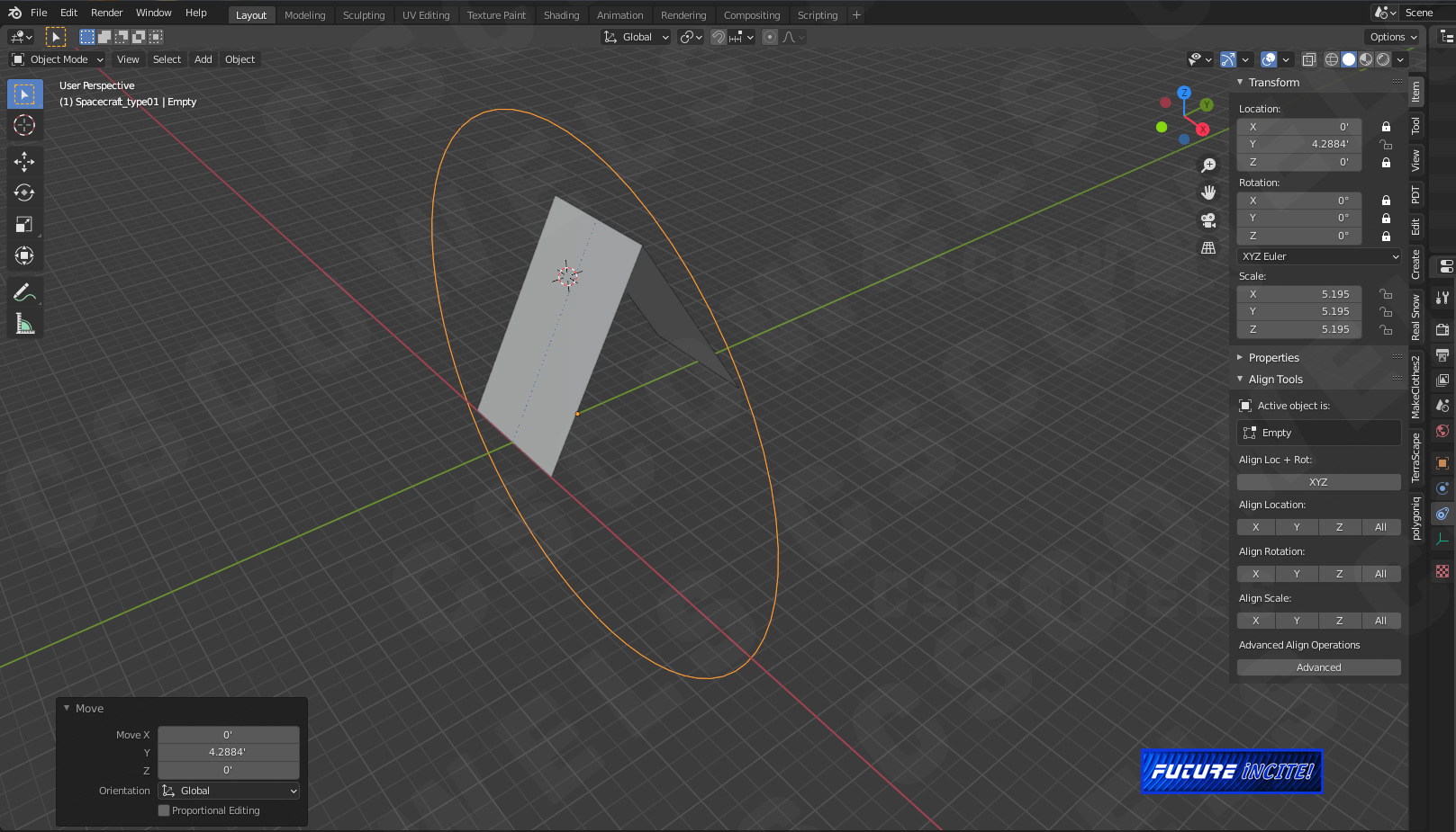
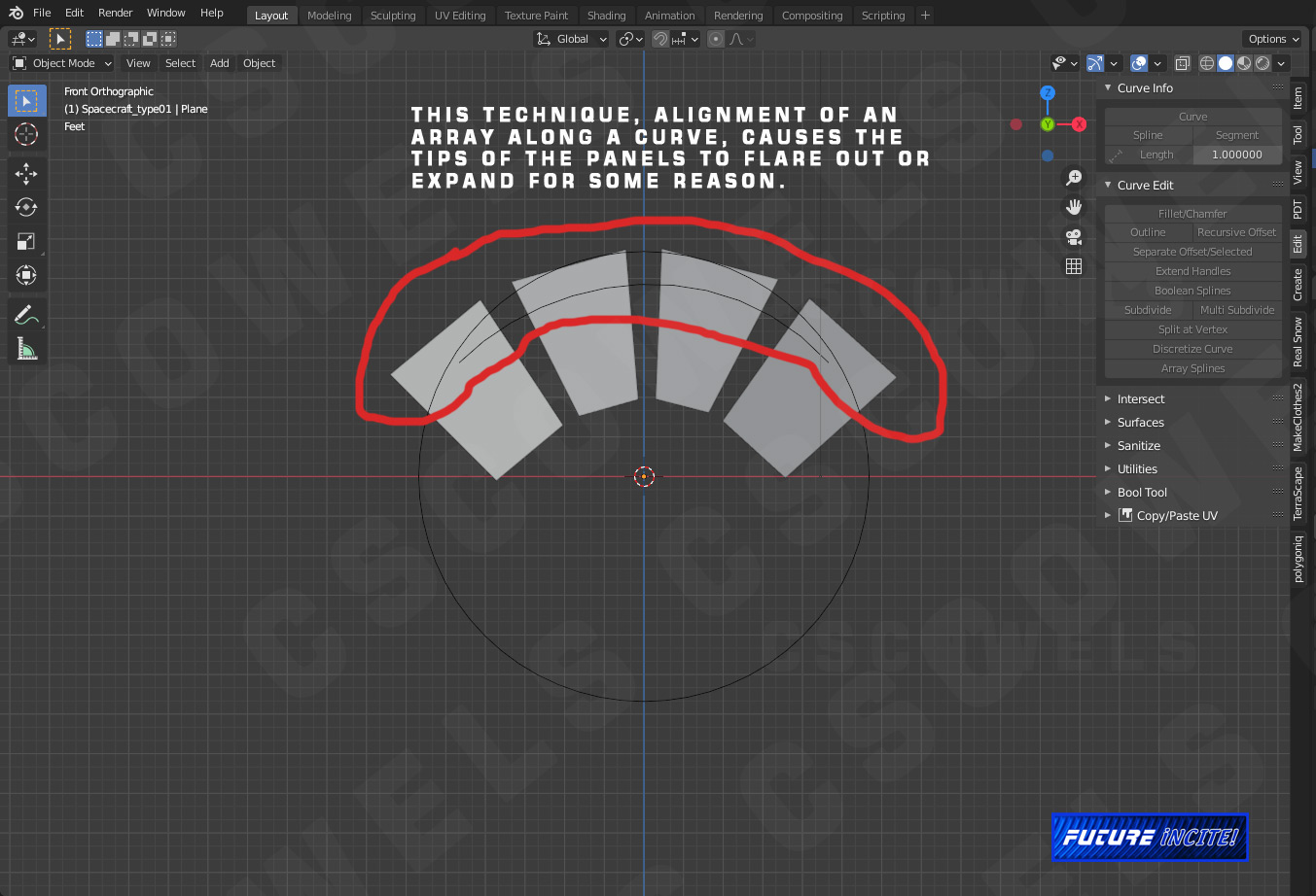
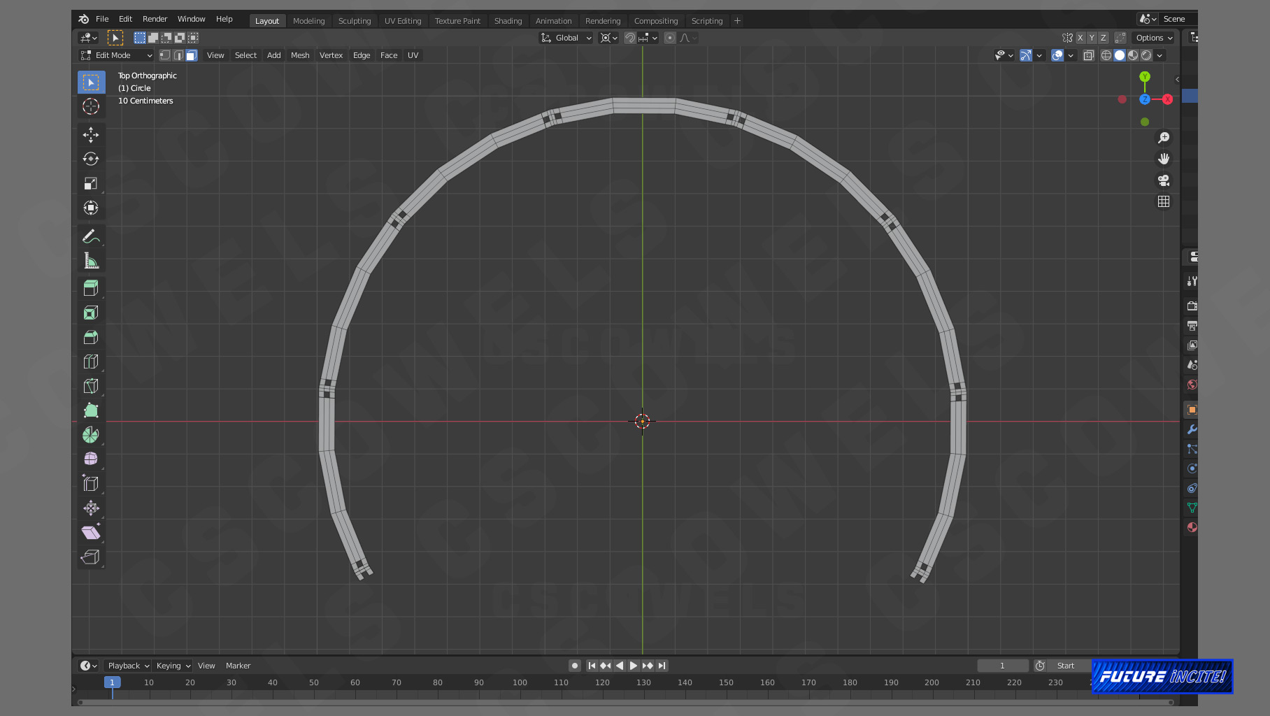
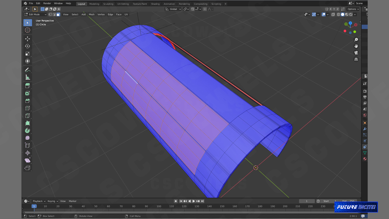
This morning I had the bright idea of making an array along a bezier curve. Hey, it’s done for treads right? What could go wrong? Unlike a tank treat, the center of the panels are at the ends, in order for them to stay in alignment. The problem arises when I animate the panels. The panels distort or “flare” at the height of the fold.
In simple terms, all I want to do it have “French doors/ Accordion” shapes fold along the arc of a half-circle, without distortion, with complete control from beginning to end with a constraint or rig.
Now, granted I could easily do this as an animation and be done with it, but I want to try something new.
Any ideas?

Happy New Year one and all!
I was able to find a tutorial that explains just how to use the Transform Constraint. \ I’ve included the link here:

Transform Constraints - Blender.org
https://www.youtube.com/watch?v=1_LcXcNnieQ

The solution to my difficulties :

  1. I had to set up an Empty and position it so that it was centered on the Origin point of the Parent Hinge Panel. This Empty was then Transformed constrained to the large Circle Empty Controller. Now, the panels open/close/fold on their local X axis, regardless of how much I pivot/rotate then on the Y axis.

  2. Checking the box next to “Extrapolation” and changing the ratio of the movement between the Controller Location and the Panel Rotation (every 10ft that the Controller moves on the Y axis, equals a 20 degree rotation on the X axis of the panel) created a smoother, more controllable action/animation.

With that settled, I decided to start forming the Intake tubes for the spaceship.
In the original thumbnails, I had designed a typical intake like an aircraft. Typical and boring. I wanted to try something new. So after a quick series of doodles, I chose a strange shape that was a mix between a automatic pistol slide and a exhaust valve to a radial prop engine.

The default cube was used as a basis. Once I stretched it out to the length I wanted,
I started fussing with the “intake” port.

This may or may not be the final form- think of it as a “white box” phase, were I am experimenting with different shapes and designs to see what looks best and what fits the universe of this particular story trailer.

The fins or radiator stacks within would be some sort of heat exchange, which would be exposed once the panels slide back (the panel prototypes are seen just beneath the intake form).
The original doodle that inspired the new shape sits beneath.

1 Like

Here are a few images of the fuselage redesign. The original is on the far right. The middle “lump” was an attempt at something a little more boxy and the unit on the left is what I decided on.

Because this is meant to be a cargo craft of some sort, I decided on a barrel shape, rather than the original streamlined structure.

This redesign started with a UV sphere that was bisected on the X axis. The rear facing section was then deleted. At first I mirrored the remaining half, but then decided to duplicate it, rotate it and move it a short distance away, connecting all of the vertices afterward. After that, I just moved and extruded the now, oval shape to my heart’s content.
The same goes for the bottom half of the barrel fuselage. Duplicate the faces and rotate on the Y axis, aligning it to the same level as the lower end of the curve at the front face of the spacecraft.

Until next update…

Okay, had a few moments today to work on this.

Extended and closed the rear of the new fuselage shape and deleted the box extensions on the sides.

Equalized the spacing of the lines on the fuselage front.

…Started to equalized the spacing at the rear but that will take a little more finesse.
The shape is not a perfect circle; the sides are flat so I will need to massage the circle shape at the rear into the oval, curved square in the middle.

I wanted to see how the engine pod base forms and the new intake design “merged” as an assembly with the new fuselage. Just moving around forms- nothing definite on that yet. I definitely will keep the new fuselage.

Until next update…

For this update I decided to work a little more on the form of the intakes. I liked the idea of the pistol slide, but still wanted to incorporate the petal like hinged panels.

I cut off the tail fins, added ribs on the side of the engine pods and added a gas rod to the intake head rear. In the above example, I had cut off the whole front of the intake, so that it could slide/recoil in reverse (forward in this case) to reveal the cooling ribs when the ship comes in for a landing.

After a few moments playing with that concept, I decided I didn’t like it because it would have put too much weight, too far forward on the slide. It might have looked cool but it just wouldn’t have been practical for such a machine. In the above image I’ve already started playing around with using the folding petal panels and wound up rigging them incorrectly.

A wireframe look at the intake ducting. They curve down before going in. I see these more like oxygen scrubbers rather than pure air intakes. The chemical processes involved when the intakes suck in particles creates heat; sort of like using carbon dioxide to make oxygen.

And here the panels have been rigged correctly (as a test) and shown in the folded position to expose the venting ribs. The fuselage form is hidden for clarity. So what I have learned is that the panels have to be rigged BEFORE they can be angled into position. I think for the final model I will create a series of panels and parent them to box empties. That way the rotation will only affect the empty and not the folding panels.

Until next update…

1 Like

The saga of the venting panels continues.
The idea of parenting the panels to an empty kept me distracted this week so I decided to “complete the thought” and give it a try.

In the above image, the panels have been modeled to what will be pretty close to the final form; added thickness with support trusses and an alignment notch to make sure the panels close properly.
The panel form on the left is parented to the four point empty, which is again, parented to the rectangle for general movement/alignment control purposes. I did not foresee the problem that this would cause until later…

Another look at the panels at full fold. I decided that the original idea of having the panels fold completely back was unrealistic and unnecessary. It would be like opening your car hood/bonnet just to regulate your car’s operating temperature. That’s why there is a radiator INSIDE the engine compartment. Plus, my reasoning is, those gas scrubbers are bound to be very expensive so no crew in there right mind would want them exposed entirely to possible damage. To that end, I decide to have the panels partially flex, to let off some “steam” so to speak. The four point axis empty is active in this image and it is rotating on the X axis. So far, so good!

Wowzers! I was so happy at this moment. I was able to pose the panels AND use the Empty rectangle controller to rotate the them as well.

Another view of the panels in face orientation mode for a better view.

And here is where the trouble started. What you see here is the second/duplicated panel vent assembly as I attempt to position it into the space above the filter/scrubbers. The first unit fit relatively well, but this one…

Zoinks!
Since I had parented the four point axis empty to the rectangle empty, if I tried to rotate the rectangle, the four point axis would also rotate and fold or open the hinge. I’m convinced the theory is sound but the intake is a curved and complex shape. I may have to go with simple angles to make this work correctly.
Until next update…

So this evening I decided to create the vent panel rig (as I have named it) in a separate blend file to reduce clutter.

This time I started the project as an extrusion instead of breaking apart a base form. It began as a 32 vertex circle which I then segmented via CTRL+R to create the shelving or shoulders for the panel doors to rest upon when they are closed.

Next comes the extrusion. No set length here, I pulled it out until it looked the “right” length."

And now, I use Loops to cut out eight segments, six of which will be the panels (three segments each for fore and aft panels).

Having rigged the center topmost panel with copy rotation and plain axis empty, I cut out the remaining spaces for the remainder of the panels.

The trick to make it work reliably this time was to simply duplicate the top most rigged panel section and rotate AROUND THE 3D CURSOR. Problem FINALLY SOLVED.

Now all there is to do is Append it to the original spaceship file and start detailing. As for now, it’s been a long day and I need to get some rest.

Until next update…

Not much of an update this go-round. Had to return to the documentary for a bit.
So I did start detailing the engine pods as I mentioned last update but decided to hold off until the complete shape is sorted out.
The fuselage shape will definitely stay and I really thought the idea of “wings” was silly. There is no way this ship could even pretend to be “aerodynamic.” I have other plans for this craft.

Anyway, I used random colors for the mesh so that should hopefully make the image clearer.

These images illustrate the amount of “flex” that I want the doors to have to bleed off heat. They will fully retract only for maintenance of the filters.

Until next update…

For this update I decided on a basic form for the engine pods. Upon creating these I began to question why a ship would need two engines on opposite sides of the fuselage… but determined to stick to the original spark of the design, I stuck with it. This iteration is supposed to be a cargo craft after all and since the rear of the fuselage will need to open, there is a use for two engines in this case.

Above is the basic form frame, minus the folding slats.

Side view of same.

Three quarter left rear view where you can see the beginnings of vents, insets and other things…

Three quarter top view rear right…

And a three quarter top view front of the engines pods and fuselage together.

Until next update…

1 Like

Did not have much time to work on this project over the last two weeks but in the spirit of progress, I scrounged a few moments for this quick update:

With the basic outside form decided upon I am blocking out the interior spaces for the living quarters and the cargo deck (seen above highlighted in orange. The image is 3/4 rear left high)

Above is the a similar view but as a solid mesh. I have extruded the shape of the cargo deck, walls and ceiling from the bulkhead mesh, which can just be seen poking through the fuselage as a series of black vertices towards the front.

So these are the basic building blocks of the interior. A n upright cylinder like form for the living quarters, a transit tube that extends from the living quarters over top of the cargo bay, and the cargo bay itself with the rear loading doors open.

And here are the engine pods alongside the living quarters. The transit tube should give a sense of the scale of this craft. I need to put a human scale figure for reference.

And last but not least, the closed clam shell doors of the cargo craft.

Another busy week ahead. Until next update…

1 Like

Sorry folks, I’ve been radio silent for a bit. Work has increased and I am finishing up a research paper. Should be able to dive back into this in mid-May/early June time frame.
Until then, “Be excellent to each other!”

1 Like

The adventure continues…
With classes and research paper behind me, I took the time to dive back into my helicopter documentary project. With that now under a full head of steam ( I was able to render more scenes in two weeks than I have been able to do in the last four years!) I can return to this project.

The original cargo spaceship idea was heavily influenced by a Star Wars type project I had considered back in the day which is now dead and buried. After re-assessing my plans for the short trailer, I took a step back and sketched out a new design (yes, the analog way- pen to paper) that makes more sense.

The above picture is the basic layout of the craft which will become clearer as the weeks go by.
This time I included a human figure for scale reference to keep me grounded.

A closer view of the human figure (actually a soldier from my helo documentary) to provide scale of how large the spacecraft will be.

Until next update!

2 Likes