Hey guys, I’m having trouble with a shape key driver. It’s for a jaw bone. The jaw bone is weight painted to the mesh, and works, but looks a little deformed, so I decided to add a shape key with a driver that toggles when the jaw bone is moved down.
The driver is properly setup, the issue is that the bone moves along the X axis in negative degrees, I can clearly see the deformation when I set it to positive degrees, but negative doesn’t work right. It’s set for 8 degrees negative, however I have to move the jaw bone practically -130 degrees to get the deformation to work O_o
EDIT: been playing with it more, and it just keeps getting more frustrating. Is there any kind of in depth tutorial for Shape Keys, Drivers, IPOs, etc? Thanks.
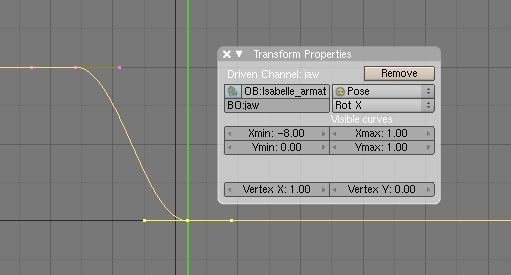
EDIT 2: Been playing moreeee… Ok, so in the screenshot where I have -8.00 for the xmin typed in, those are like, units, not degrees, I need to actually look at the degrees in the gui? Is there a more precise way to do this? I would rather type them in if possible?
When reading the Transform Properties panel in regards an IPO curve, the X dimension is the time factor, i.e., frames. So the Xmin = -8 means that the least frame value in the IPO curve is -8, which seems to be the case looking at the image posted. Xmax = 1.0, or frame 1, which also jibes with the image.
All “operative values” for transforms, such as Location units, or Rotation units, are measured along the IPO curve’s Y axis. So, for the curve shown the values go from 1.0 at frame -8 to 0 at frame 1. Which transform (or shape key influence) the value applies to is determined by the “channel” the IPO curve is applied to.
I haven’t used driven shape keys in this manner so I can’t help set that part up, but this info should clarify how to read the Transform Properties data.
Regarding unit values in the Transform Properties panel of an IPO Editor window, for Euler rotation, the value to enter is 1/10 the degree value you want, so for 340 degrees, you;d enter 34.0. This will be the Y value for the curve at that point. The scaling of the value is I think to keep the resultant curves within the same approximate scale as values for Location, so they’re easier to read when switching from one channel to another in the IPO Editor window.
Bones use Quaternion rotations, however, so the values for the three axes shown in the IPO Window Transform Properties panel will not match those in a 3D Window Transform Properties panel even after scaling for the 1/10 factor – in the 3D window the values are “Eulerized.”
If you typed -8 in the Xmin field of the Transform Properties panel open in the IPO Editor (as shown in the image you posted), then you’re setting the minimum frame value for the IPO curve to -8 frames, which cannot be accessed for playback, because the Timeline starts at frame 1. Xmin in this context has nothing to do with the object’s transform along the X axis. To affect the X axis transforms, you’d have to create an IPO curve for that channel (such as RotX or LocX), and use the IPO curve’s Y axis to set the actual transform values, or use the driver setup to determine these values. I assume that for shapekeys, the RotX value of the driver bone will determine the Y-axis value for the shape key, which will vary between 0 and 1.0, it being a normalized value range, but since I haven’t used this technique, I can’t say for sure that’s the case.