I am planning a floor for a building. This floor needs to be regular cleaned with water. So i am doing an slope design for this floor. Every surface shoud have at least 2 percent gradient to a specific direction. Because of the complex geometry of the room, i wonder if i could do a visualisation of the gradients to check if every face have at least 2 percent gradient.
It would be very cool to do such a thing inside blender.
Is this for the real world? A 2% Slope would be roughly a 1/4" rise per foot of run! Or 1 foot rise in 50 feet of run! That wouldn’t even be comfortable to try and walk on! Just saying.
I don’t know how complex the room is to be so that would be a design challenge if all areas are to slope to a single drain.
But for a single plane, something like this would give you a visual ( you could also use one of the checker textures from UV unwrapping )
This is looking promising. But it seems, that the gradients are calculated to the next face. But in my situation they need to be calculated to the horizontal line.
I know, its not easy to describe the problem in math. Or at least to translate this into blender nodes world.
In the screenshot you see blue faces with a higher gradient. Achieved with the node setup you see below, based on your proposel. But some faces are not coloured properly. If you look at the plane with one point in the middle, you see that the coloured faces are depending on the objects rotation, altough they have the same difference in heights.
It would be awesome if you could explain how to achieve this calculation, which is not depending on the obects rotation, but only the gradient depending on the height difference.
Percent of slope is determined by dividing the amount of elevation change by the amount of horizontal distance covered (sometimes referred to as “the rise divided by the run”) and then multiplying the result by 100.
This is where you are going to run into problems…
Say you want a 2% slope to all 4 walls of a room, with the 0,0,0 at the center ( 0,0,0 being the drain) and the room is 15’ x 12’ you get…
So short walls will be considered a cross slope with the same 2% … you will have to decide if you want to go with the Lower Rise or the Higher, or if you want to go with the median of the 2.
Hi iRolf,
instead of using the Normal i maybe should have used the True Normal so it won’t get affected by smooth shading sorry about that.
As @RSEhlers already mentioned, your slope percentage is basically the result of a tangent function.
For example: If you see a street sign that says “20%” you know that when you travel 100m horizontally you will have to go 20m up or down.
I tried to illustrate the result of the dot product on the following image:
Because the Normal Vector and the Up Vector are normalized (length = 1) you can just use the result of the Dot Product to calculate the slope angle with an Arccosine function . And if you know the angle you can simply calculate the slope percentage with a Tangent function.
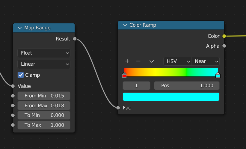
To change the colors depending on the slope percentage, put some markers on the color ramp where you want the color to change. The position will be the slope percentage as a value → e.g. 2 % = 0.02
The Map Range node is not necessary but it gives you some controll to space out the markers on the color ramp a little bit (so they aren’t as close together as they are right now).
I couldn’t replicate your problem with objects rotated around the Z axis…
Be aware that there’s maybe some precision error using this setup (couldn’t figure out where the problem comes from though…). Maybe the difference between 1,5% and 1,8% is to small?
Edit: Forget what i wrote about the Map Range node and the precision error. Put your min and max slope percentage in to the From Min and From Max of the Map Range node and put the markers of the Color Ramp to 0 and 1. That should work just fine: