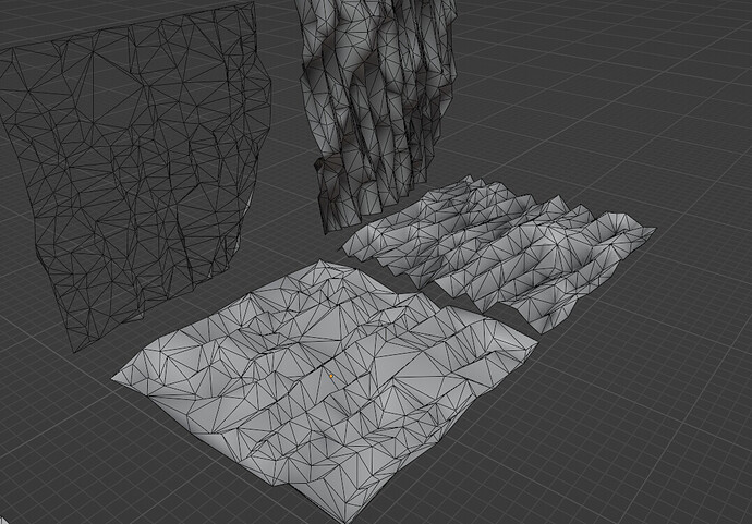
Here’s a case for research - smart adaptive vertex displacement.
What does that mean? I’m making a scene where I use height textures as displacement maps for surfaces, and these surfaces need to be low poly, while still having shapes follow the texture map. I use very high subdivision for that and then decimate it, so it’s somewhat what I want to achieve.
The problem is it’s very slow, adds more inconvenience to editing the surfaces. So I thought - what if I could just offset vertices so they would be placed at peaks/holes/slope tops of the displacement texture?
And I don’t know how to progress further with it.
Maybe there’s already a formula or nodes for that, idk, can’t find them. Some help would be appreciated.
It looks like a chicken and egg problem, to find the peaks and holes you need to sample the texture and for that you need a mesh with enough resolution.
You can look at that : Tenochtitlan (wip) - #4 by ThomasKole
For adaptive subdiv according to a map, it’s slow to compute too but might sparks some idea !
Good luck !
I might try this method, it’s basically spawning points and rebuilding mesh from these, but how well can it preserve UV and vertex colors, as well as still keep mesh in shape (it doesn’t ruins walls, floors, etc)?
It’s possible to sample texture at different coords with geonodes, no need for more vertices for it. The problem is to figure out the formula how to move the vertices.
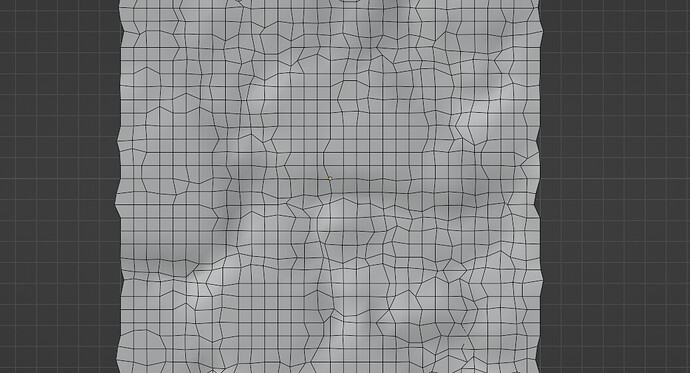
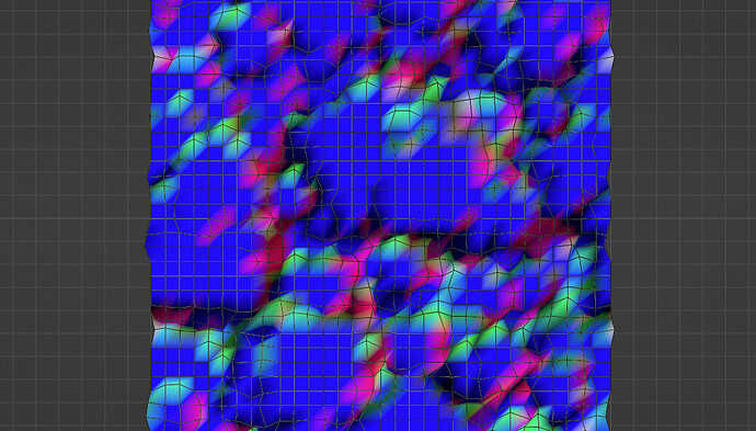
I experimented a bit - I generate a normal map from the height texture then shift vertices by color from the map, and correct the UV. But not really sure how to make it keep results consistent and accurate, there are some tradeoffs.
So I tried method from the post you linked and it’s not usable for non-flat surfaces.
It would need another Delaunay-like method to insert vertices on faces, with interpolating attributes too, not sure if possible at all with current node functionality.
yeah, you need to unwrap the mesh first so you work in 2D, then generate the mesh, then put it back in place
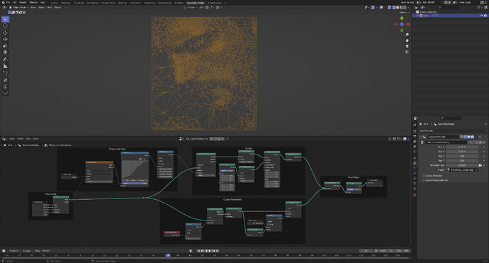
Here’s a way to control the density of a mesh based on the value of a grayscale texture:
This works only on flat geometry, as it uses the Fill Curve node, which flattens everything to the XY plane, but I think for displacement this might be good enough. Note that the density of the “Main Grid” controls how precisely the input map is sampled. Also, the density and distribution of the points that control the subdivisions, is controlled with all the nodes in the Greyscale Map group.
This is based on the triangulation node tree by wafrat.
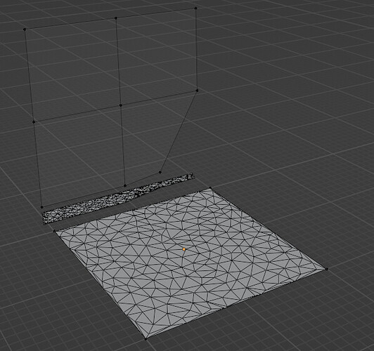
So I tried this method and added the position unwrapping from post above as well, additionally created edge detection graph for the height texture and… result doesn’t look good.
Top - high subdivision and decimate
Bottom - triangulation method
Are you using the height map to drive mesh resolution as well? Because that wouldn’t work. After all, darker values only mean that those parts are lower than lighter values, not that there’s supposed to be less detail. I’m not sure how the height map needs to be processed to work for this. Calculating curvature from it, maybe? Edit: Ah, I see, you are already using edge detection.
I did some progress - instead of plugging edge map into density, use delete points node after distributing it, where edge map is used for the deleting selection, then merge by distance. Seems to be working, I’ll see how further development goes.
Well sadly it’s still not as good as subdivide+decimate method. There are places where it misses the shapes and doesn’t take the curving into account, and there are some ugly deformations as well.
I’m not sure how I’d progress it, edge detection and deleting points can only take it so far, there’s more nuance to figure out.
