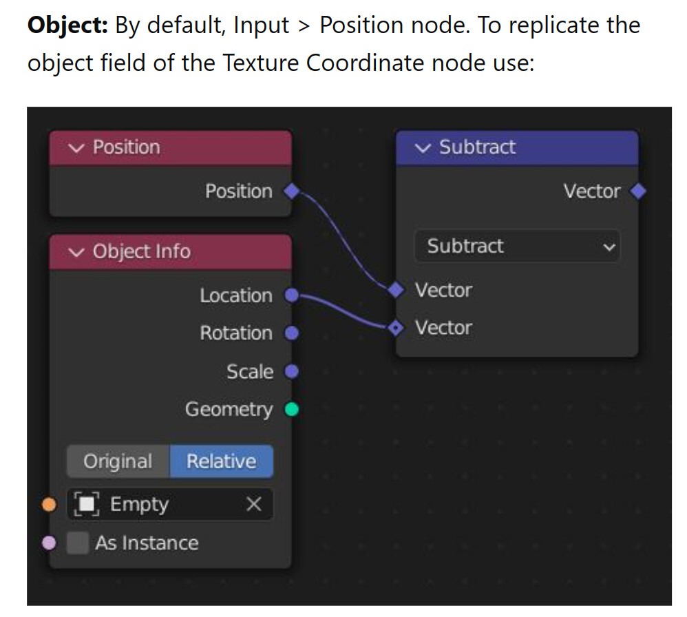
What does that node chain mean?
Why subtracting the Location of the Imported Object from the Position of the Imported Object? ()
Also, Is there a distinction between the Position and the Location in Geometry Nodes? Is the Position the location of the Imported Object in Global Coordinate System, and what does the Location data mean? Why subtracting Location from Position?
In Shader Nodes, Object Texture Coordinates simply means using the Imported Object’s coordinates as Texture Coordinates, with its yellow dot as the Origin. So, how does this node chain recreate that?
Thank you!
Blender Developers, if you’re reading this, please add a Texture Coordinate to Geometry Nodes as well, because Geometry Nodes also uses textures, not just Shader Nodes. Thank you.
In Shaders, the Position is in World space (not in GN nodes, though). To get the Object coordinates, you need to transform the world space into object space. Your example, is not quite right, because you’re just dealing with the translation of the space origin (position - location). That won’t take into consideration the object space rotations, and a better alternative is to use the VectorTransform node.
Basically, if your object has its origin at Vector(2.0, 2.0, 1.0), their vertices will have their ObjectCoordinates added to that vector, when you read the WorldCoordinates. To revert that, you need to subtract the origin location from the vertices position (in world space), so that you get the position in object space.
Question 1.
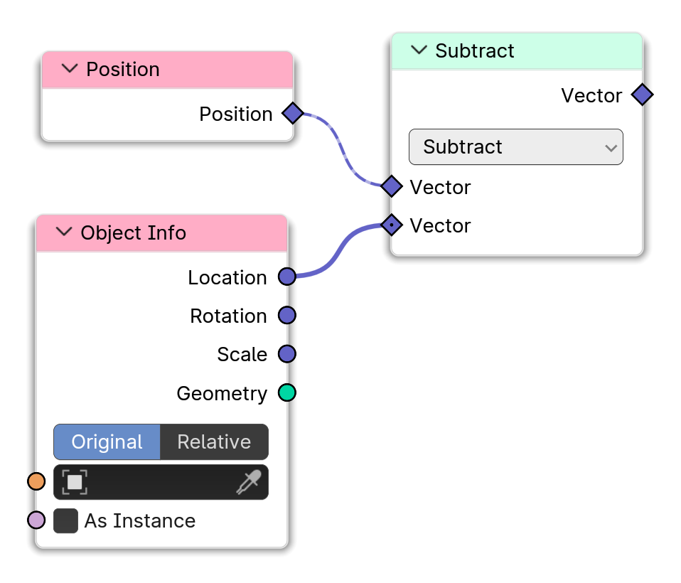
With Object Texture Coordinates, I see that you abandoned the “subtracting away Imported Object’s Location” part and just simply used the data of Position.
Could you please elaborate your decision? Is it because I said I don’t wanna use the Empty?
Question 2.
Your approach of Object Texture Coordinates is simpler and will likely be what Imma use, but I still need to understand their approach. Please help me if you don’t mind.
And this subtraction would do that?
Sorry, just to make sure, the Origin here is the yellow dot?
So that would make sense to subtract the Imported Object’s Origin instead of an Empty like here, wouldn’t it?
Question 3.
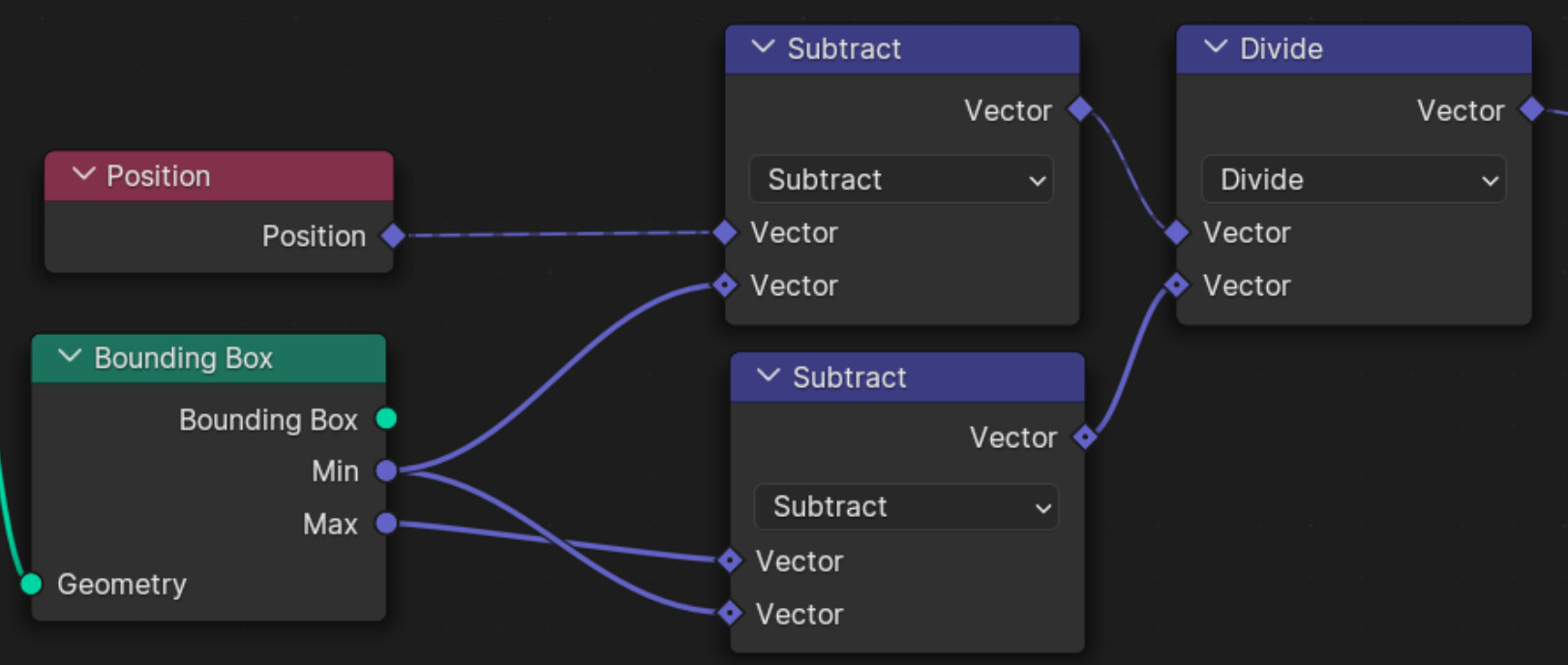
I’m struggling to understand your Generated Texture Coordinates. Please help me understand.
What is the distinction between your approach and the StackExchange’s approach? I can understand the StackExchange’s approach but I fail to understand yours.
StackExchange simply remapped the Imported Object’s Bounding Box’s Min and Max to (0,0,0) and (1,1,1). Which is pretty intuitive.
You subtracted Min of Bounding Box from Imported Object’s Position, subtracted Bounding Box’s Min from Max, and finally divide the second subtraction from the first subtraction.
As I mentioned, the position vector in GN is in Object space, so no need to make anything with it.
In GN: It will subtract the “Empty’s” location from the position of all vertices. If you use this subtraction in a SetPosition, you’ll see that your mesh will now be in an opposite side (the negative coordinate) of the “Empty”, in relation to the origin of the object.
(it will move the mesh in relation to the objects origin, the same ammout as the object’s origin to the empty’s origin.)
Yes.
Not if you have ‘Relative’ ticked on… then the relative location of your object will allways be (0.0, 0.0, 0.0) and we know that subtracting zero from something, does nothing!
What StackExchange’s approach???
Well, the math behind a MapRange (i suppose that’s what you refer) is the same as what I posted…
The bottom Subtract gets the difference between Min and Max.
The top Subtract resets the position to Min, and the Divide, normalizes the difference into a [0, 1] interval (x / x => 1).
If you want to hide all logic behind a ‘intuitive’ interface, you’ll probably never understand what’s going on, and we will have much more questions about this in the future!
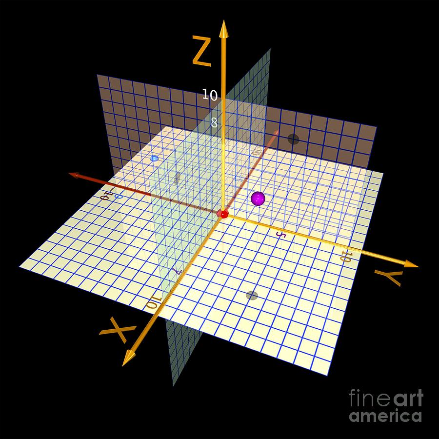
I can’t know for sure that you’re a visual learner, but I think you may need to solidify a mental image of what exactly coordinates are. Once you’re able to visualize them, everything else flows naturally. When you think of a set of coordinates in 3d space, imagine it as a point sitting somewhere in there :
With this as a base, you should be able to see the different relationships between math operations on coordinates and what they mean in terms of transformation : subtractions move things, divisions scale them down, multiplications scale them up, and so on and so forth. My advice for getting better at this, is to use the viewer node (ctrl+shift+click on a node). It shows values of the connected attribute, so 0 is black and 1 is white, and anything in between is some shade of grey. If you connect the position node to a viewer (or specifically one component of it, one axis) and put some math in-between, you can visualize what each operation does in a visual way.
With object cords you can use either your objects origin or the origin of any other object as the 0,0,0 point.
The example with the empty is using the empty’s origin as 0,0,0 instead of your objects origin. Subtracting the location of the empty from your objects position gives you the offset of the empty’s position from your objects position.
As you did not want to use the empty’s origin there is no need to subtract anything from your objects position in the geometry nodes. The position of your object gives you the object cords.
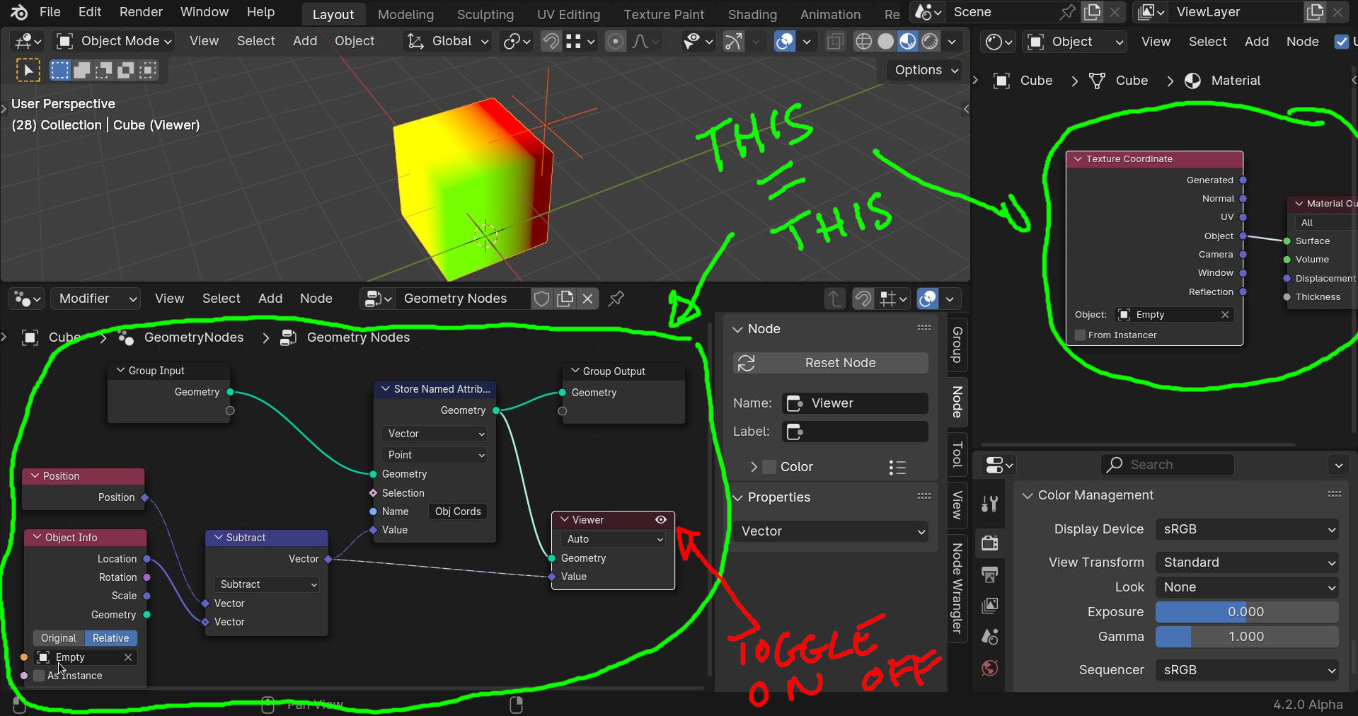
You can visualize this with the viewer node in geometry nodes. Set colour management to standard-node, set up a material with just the texture coordinate node straight into the material output and go to material preview in the 3d view.
First using the empty as 0,0,0 use the subtract method and object info of the empty in the geometry nodes and in the shader nodes set the object coordinates object as the empty. Toggle on and off the viewer node to compare the 2 results (they are the same)
Now if you do not want to use the empty, get rid of the subtract and the object info node in the geonodes and simply use the position of your object. In the shader nodes delete “Empty” in your object coordinates.
Thank you for being thoughtful, actually I do know what Math is, I’ve had a few years experience of doing Procedurally Modelling / Vector Displacement in Shader Nodes and this is my first time touching Geometry Nodes. How Maths work in Shader Nodes and Geometry Nodes can be different, hence the questions.
For example, as Secrop pointed out, “Position” output in Shader Nodes uses Global Coordinate System but the one in Geometry Nodes does not.
Solid advice, thank you, didn’t know about the Viewer Node.
It’s intuitive, to me. Or, understandable, to me.
I’m not trying to downgrade the importance of your approaches and explanations, I’m just saying that their approach is Mathematically intuitive to me, so that you can be aware of what I understand to use it to explain to me further.
You use Math to explain, correct? So I need to tell you what Math that I understand so you can be aware what level of understanding I was at, to help me go further from there.
What I was doing, is trying to tell you: “Hey I’m half way there, you don’t have to walk me from the start, but walk me from where I’m at, to the destination”.
Awesome! Thank you for answering my question! Thank you for helping someone who doesn’t understand. Exactly what I need.
You are knowledgeable and have good intentions, but not everyone is as well knowledgeable as you are. Some people have things that they don’t understand, that’s why they ask. The world would be doomed if helpers get mad everytime they receive a request, especially when the person who needs help lowers themselves and politely asks for help everytime.
Don’t get me wrong. I’m not mad… I just expect a little effort from the person who’s asking, in trying to understand the problem. Learning and teaching go hands in hands, and this is true not only to the person with questions but also to those with answers.
I know that we are all different, and our learning process is, at the most, a strange hidden process in our subconscience. As Hadriscus said, some are ‘visual learners’, others need to ‘touch and feel’, or use any other mechanism, in order to assimilate something new… Oh well, some haven’t yet found their own best way to learn!
Anyway, such situations can be minimized when the common language has the same basis. And Hadriscus has also a point, when he refered the documentation. We know the docs aren’t perfect, but they give us concepts that we can use to better communicate our doubts, problems and solutions.
Hi!
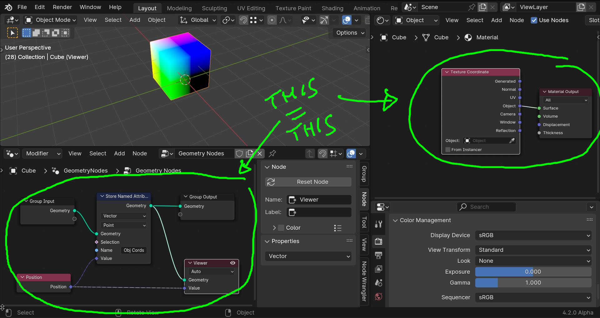
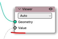
Sorry, we can’t preview Vectors values (the red, green, blue) in Geometry Nodes, can we? We can only view Vectors values in Shader Nodes, and there’s only Scalar values preview available in Geometry Nodes, right?
In your Geometry Nodes screenshot, I see that you have blue color as input to Value socket, which indicates that Vector values have been inputted, and is likely to be displayed (isn’t it?). Whereas my Value socket only shows gray color, which indicates that Scalar values have been inputted, and as expected, it only displays Scalar values.
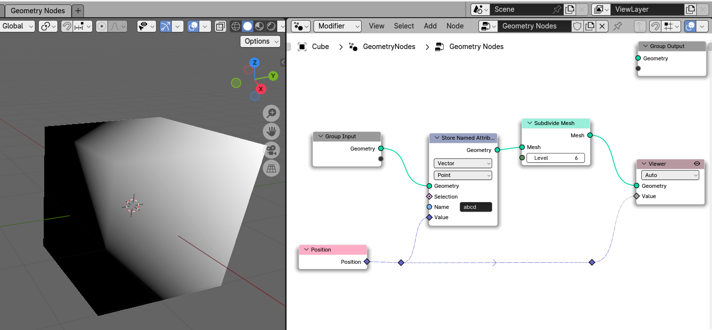
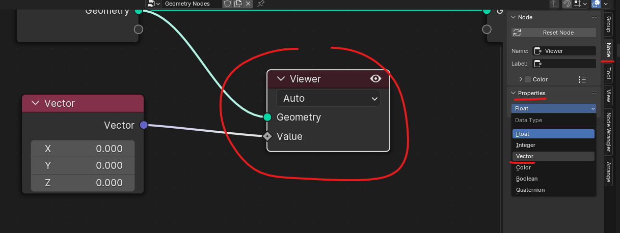
Of course you can, but your viewer Node is set to display Float values, not Vectors:
You can change the Type of the Viewer node in the Side panel (press N on your keyboard to open it):
About that, I find it frustrating that the type can’t be automatically inferred like the domain is. I wouldn’t want it all the time (sometimes you really want to cast one type to another for convenience), but it would be handy.
Yes, it’s not clear-cut when things should appear on the node or in the sidebar. It’s only a few nodes that do this too, so you seldom think of looking there. I think it’s justified for whole-ass interfaces like simulation baking (which lives on the simulation output node alone), but not for stuff like this.
My understanding is, fields that aren’t yet stored as attributes could exist on any domain, so Blender can’t really know what you want.
if there are only instances in the Geometry and i want to view the Instance Rotation it would be nice to automatically view the values from the Instance domain
Thank you. It works great. That’s very inconvenient, however. I hope that the Developers could make the Viewer node automatically realizes what type of data that it is receiving and displays that type of data correspondingly, just like what Material Output node in Shader Nodes can do.